
Rancilio Silvia Auber PID install, step by step
A full walk-through of installing an Auber PID on a Rancilio Silvia. Mains voltage inside; read the safety block first.
Prerequisites & tools
- Tools: multi-bit screwdriver, 20mm wrench, wire strippers, multimeter, crimp tool, heat-shrink.
- In the kit (Auber SYL-1512A or similar): PID controller, SSR-25DA, PT100M RTD, wiring harness, zip ties.
A full walk-through of installing an Auber PID on a Rancilio Silvia - from unplugging to dialing in the first shot. Mains voltage inside; read the safety block first. Photos are placeholders while we shoot our own.
The short answer
An Auber PID on a Rancilio Silvia takes 2-3 hours: kill power, drain your boiler, pull both factory thermostats, seat a PT100M RTD, mount an SSR on that pump panel, wire heating loops, land PID terminals 1/2/4/7/8/9/10, set SV 228-229°F, pull a shot.
Installing an Auber PID on a Rancilio Silvia is an afternoon job. Unplug, drain, strip the cover, pull both bimetal thermostats, and reuse one as high-limit. Seat a PT100M RTD, mount an SSR with thermal grease, wire it in series with both heating loops, tap main power at your wall switch, route leads through that rubber grommet, land terminals 1/2/4/7/8/9/10, set SV 228-229°F, P 1.8-3.5, Tp 0.7s, then pull three shots to confirm ±1°C stability.
This guide walks the full Auber install on a Rancilio Silvia: teardown, thermostat pull, RTD seating, SSR mount, terminal landing, parameter tuning. Eighteen steps, twenty photos pending, every safety block earned from actual bench time.
Prerequisites & tools
Difficulty: medium. Time: 2-3 hours. You're inside the mains power path on a brass-boiler machine - if you're not comfortable with basic electrical safety, stop here and pay someone who is.
- Tools: multi-bit screwdriver, 20mm wrench (for the OPV if you calibrate), wire strippers, multimeter, crimp tool, heat-shrink.
- In the kit (Auber SYL-1512A or similar): PID controller, SSR-25DA, PT100M RTD sensor, wiring harness, zip ties.
- Not in the kit, but handy: magnet mat for screws, phone for photos before you disconnect anything, thermal paste for the SSR.
Silvia Auber PID Install — What You're Getting Into
This is the thermal control rebuild. It's the foundation mod that makes a Silvia worth drinking from. The factory runs on two mechanical bimetal thermostats with a deadband wide enough to drive a truck through — shot temperature wanders between scorch and sour across the morning. An Auber PID with a PT100M RTD in the boiler thermowell and an SSR taking over AC switching locks water temp within ±1°C. That's the difference between "is it me or the beans?" and pulling the same shot twice.
This is an L2 job. You're inside the chassis next to 120V or 240V mains, a brass boiler that holds a heat charge, and heating element pins that have cooked every shot for a decade. One wrong wire and the breaker trips — or worse, the shell stays hot with no cutout. This guide covers the full Auber install: teardown, thermostat pull, RTD seating, SSR mount, terminal landing, and PID parameter tuning. It does not cover OPV calibration, pump damping, or Gaggiuino. Those live in their own guides.
Step 1: Lay Out the Kit and the Tools
Open the Auber box on the bench before you touch the machine. You want the PID controller, the PT100M RTD probe, the SSR with its heatsink pad, the piggyback power tap, the thermal grease sachet, and the rubber grommet. Count them now, not at reassembly when the grease has rolled under the fridge.
Hand tools: 2.5mm and 3mm hex keys for the top cover screws, a stubby flathead for the thermostat spring clips, a multimeter with ohms, wire strippers, crimp tool, heat-shrink, and a 20mm wrench. The wrench isn't for the PID — it's for the OPV brass locknut sitting right there once the cover is off. Most of us do both mods in one sit, so have it ready.
Missing the grease is the usual rookie mistake. The SSR will thermal-cut inside a month without it.
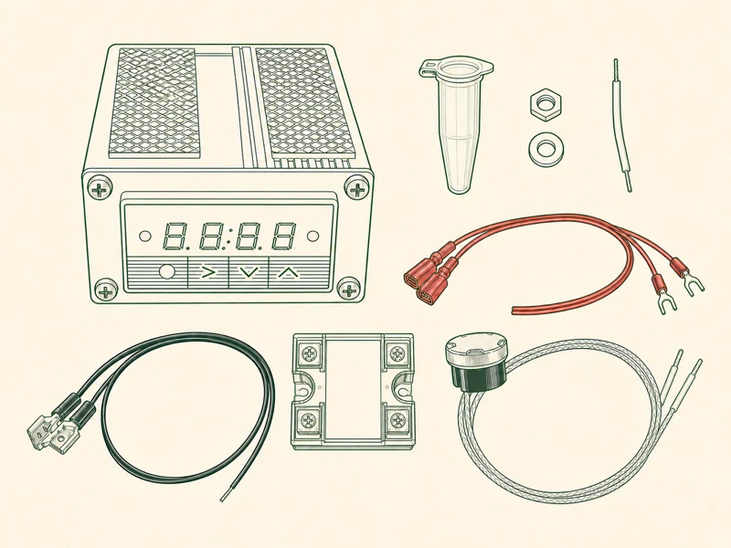
Key takeaway: Inventory every kit part on your bench before touching the machine; that grease sachet always goes missing.
Step 2: Kill Power and Drain the Boiler
Unplug the machine from the wall. Not the front switch — the wall. Then pull the water tank and run the brew switch with a cup under the portafilter until the pump gulps air. Silvia's boiler holds enough residual water to short a screwdriver to the chassis if you skip this.
On older machines there's a bleeder valve on the boiler top; crack it after draining to break the vacuum so the boiler doesn't suck air through the element seals when you open it up. If the machine has been sitting cold for an hour, you're fine. If it just ran a shot, wait.
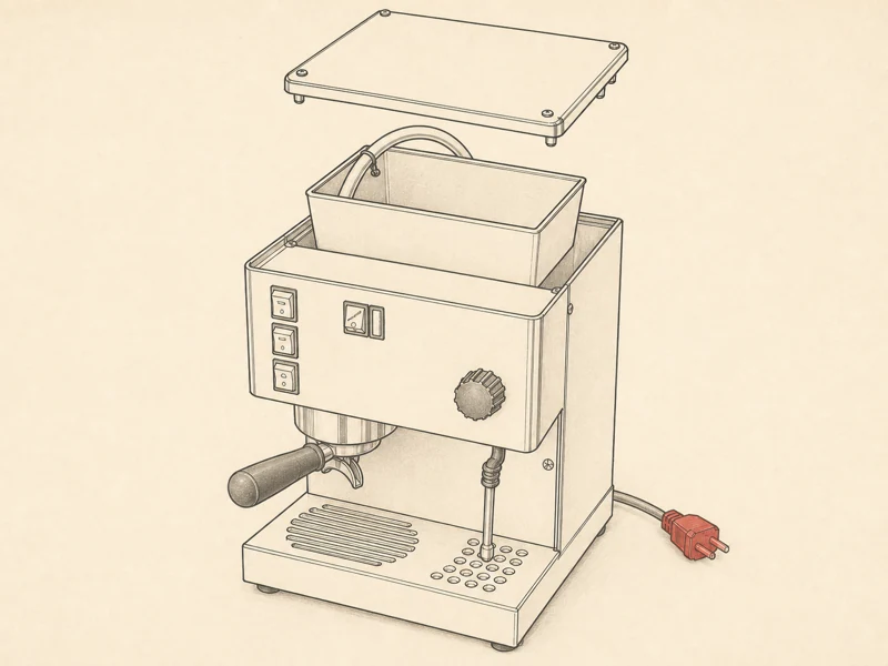
Key takeaway: Pull the wall plug, drain your boiler through its portafilter, and meter element terminals dead before any chassis work begins.
Step 3: Strip the Top Cover and Rear Baffle
Four hex screws on top, two on the rear baffle. Lift the top cover straight up — the steam wand and water spout pass through rubber grommets that resist, so rock it gently side to side. Set the cover somewhere it won't get scratched. The powder coat on these chips if you look at it wrong.
The rear baffle is the thin steel plate between the boiler and the back panel. Two more screws and it lifts out, exposing the wiring chase where all your new wires will route. This is also where the OPV assembly pokes up through the boiler top — if you're doing the 9 Bar calibration in the same session, this is your access.
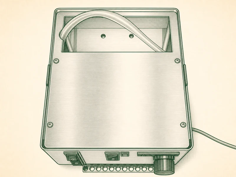
Key takeaway: Four top screws plus two on the rear baffle; lift straight up, rock grommets gently, set that cover where it won’t chip.
Step 4: Map the Two Factory Thermostats
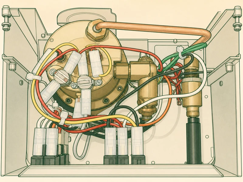
Look at the boiler top. Two bulbs poke down into thermowells, each held by a spring clip and a push-on spade terminal. The left one — usually with a red mark on the spade — is the brew thermostat. The right one is the steam thermostat.
Both are mechanical bimetal switches with roughly a 15°F deadband each. They click on and off based on shell temperature, not water temperature, and they're slow about it. These two components are the reason your shots taste different every morning. You're about to retire them from active duty. The Silvia deep guide breaks down the full thermal chain if you want the why before the how.
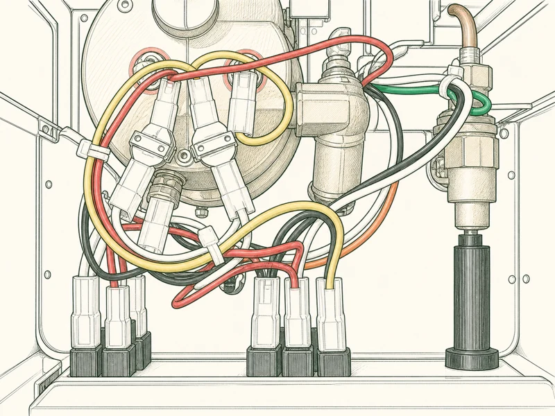
Key takeaway: Two thermowells, two bimetal thermostats, 15°F deadband each; that red-marked spade is brew, the other is steam.
Step 5: Pull the Steam Thermostat
Stubby flathead under the spring clip on the right thermostat, lever up. The clip pops off and the thermostat lifts straight out of the well. Pull the spade terminal by the boot, not the wire — the crimp is weak and the wire will yank out of the boot before the spade lets go.
Set this thermostat aside. You're going to reuse it in Step 6, relocated to the brew-side well as a mechanical high-limit. The Auber kit doesn't waste good parts.
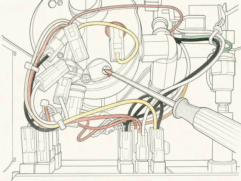
Key takeaway: Lever that spring clip on your right (steam) thermostat, lift straight out, save it for Step 6 relocation as a mechanical high-limit.
Step 6: Pull the Brew Thermostat and Relocate the Steam One
Same clip-and-lift on the left side. The brew thermostat comes out and goes in the parts bin — the PID takes over brew temperature control via the SSR, so this thermostat has no job anymore.
Now take the steam thermostat you just pulled in Step 5 and drop it into this left thermowell. Clip it in. Sounds redundant to reuse a mechanical thermostat you just removed. It's not. If the SSR ever fails shorted closed — and solid-state relays do fail closed, that's their failure mode — this relocated thermostat is the mechanical cutoff that kills power before the boiler runs dry and the element burns through the shell.
The right thermowell is now empty and waiting for the RTD.
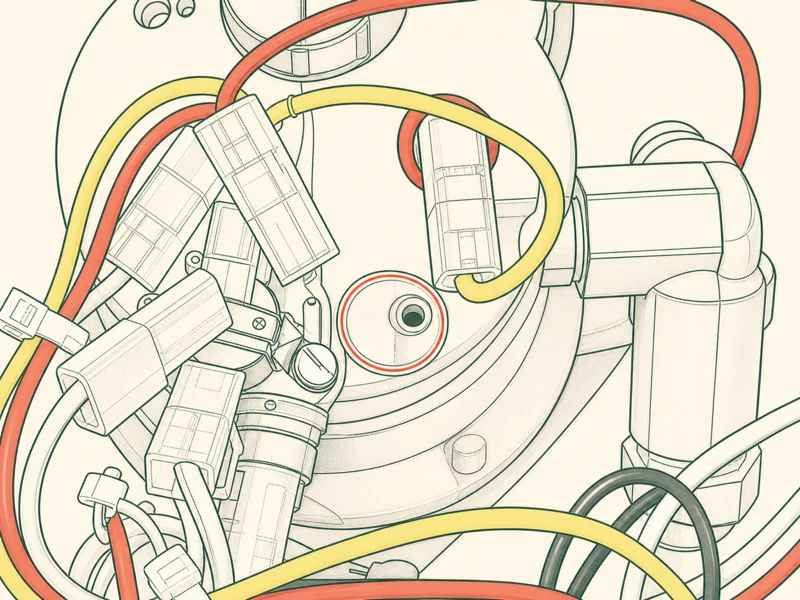
Key takeaway: Pull your brew thermostat, drop that steam one into the left well; if the SSR ever fails shorted, this mechanical cutoff saves your boiler.
Step 7: Meter the PT100M RTD Before You Install It
Before you seat the probe in the boiler, meter it. Set the multimeter to ohms and touch the two RTD leads. At room temperature you should read 100–140 ohms. A PT100M element is nominally 100 ohms at 0°C and climbs from there, so 108–115 ohms at 20°C shop temp is normal.
If you see open line or a dead short, the element is broken. Do not install it. Contact Auber for a replacement — they're fast about it.
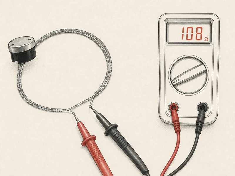
Key takeaway: Meter the RTD before seating; 100-140 ohms at room temp is healthy, open or dead short means call Auber for a replacement.
Step 8: Seat the RTD in the Cold-Side Thermowell
Drop the PT100M probe into the right thermowell — the one closest to the cold water inlet, where the steam thermostat lived. Push it to the bottom of the well. The right well gives the PID the fastest read on incoming cold water hits, which is where brew temp stability actually lives. The left well, now holding the relocated thermostat, only sees post-mix temperature.
Route the RTD lead along the boiler shell following the existing harness. Zip-tie to the factory anchor points. Don't let the lead touch the heating element pins or rest against the element terminals — the insulation on those leads is rated for boiler temp, not for direct contact with 120V AC pins.
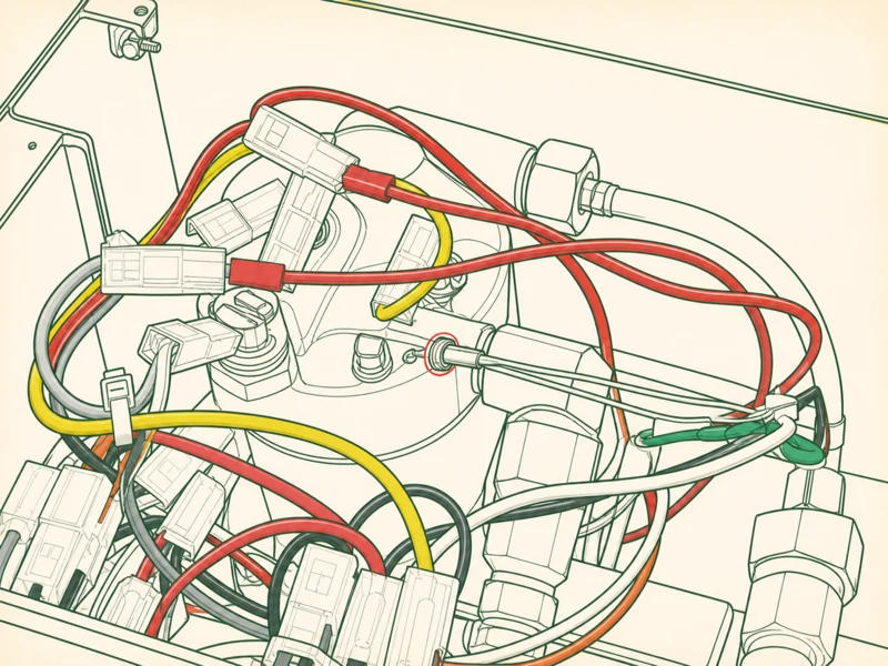
Key takeaway: Seat your PT100M in that right (cold-side) well for a fast read on incoming water; zip-tie leads to factory anchors, never let them touch element pins.
Step 9: Prep the SSR Mount on the Pump Panel
The Silvia chassis has a pre-drilled hole on the left-side water pump protection panel — that flat steel plate shielding the Ulka vibration pump from the boiler compartment. That hole is Auber's specified SSR mount location. It's not a coincidence; Auber measured the Silvia chassis before they tooled this kit.
Clean the mounting surface with isopropyl alcohol. Any oil film or dust under the SSR base adds thermal resistance, and the SSR dies at its internal thermal limit. Dry-fit the SSR, confirm the hole lines up, and look underneath to make sure you can get a nut and washer on the back without the screw hitting the pump body. If the screw is too long, it bottoms on the pump — grind it shorter or use the supplied hardware.
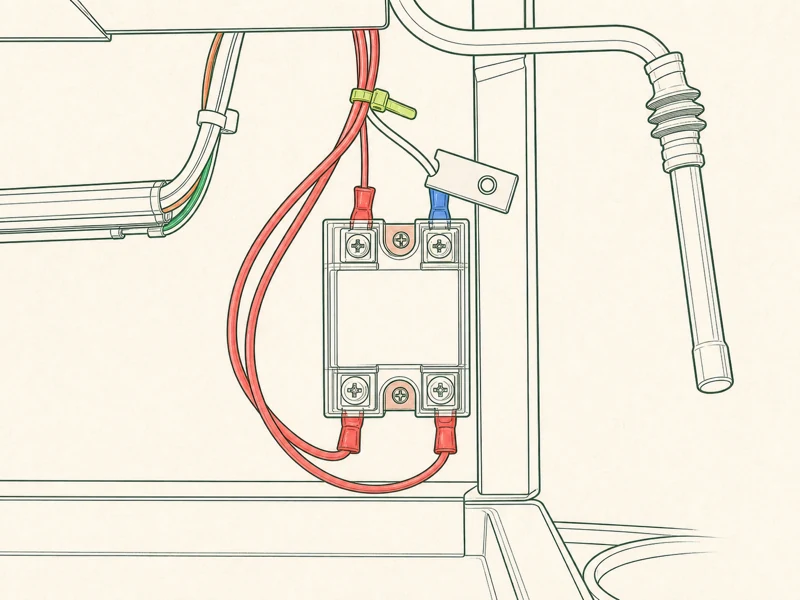
Key takeaway: Auber’s specified SSR mount is that pre-drilled hole on your pump panel; clean it with isopropyl, dry-fit, confirm screw length clears the pump body.
Step 10: Grease and Bolt the SSR
Smear a thin, even film of thermal grease on the SSR base — pea-sized, spread with a credit card or the flat of a spudger. Too much is worse than too little. Excess grease pumps out over thermal cycles and leaves an air gap under the relay, and an air gap is an insulator.
Seat the SSR, drop the screws through from the top, washer and nut underneath. Snug by hand, then a quarter turn with a driver. Do not crank it. The SSR housing is cast aluminum and cracks under over-torque, and a cracked housing lifts the base off the heatsink pad and recreates the thermal problem you were trying to solve.
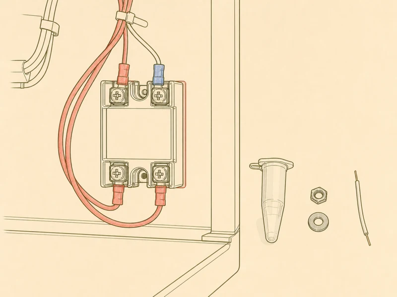
Key takeaway: Pea-sized grease film, spread thin; snug by hand plus a quarter turn, never crank it — cast aluminum cracks and lifts the base off the heatsink.
Step 11: Wire the SSR Into the Heating Loops
The SSR splits into two independent control domains. The left domain — two black output wires plus the main input — handles steam temperature. The right domain — two thick red output wires plus the main input — handles brew temperature. Keep them straight by wire color, not by memory.
Cut the factory heating element leads and crimp the SSR outputs in series with each loop. Polarity on the AC side doesn't matter for function, but keep the brew and steam loops physically separate. Cross them and your steam switch fires the brew element, which means the boiler hits brew temp on steam command and your milk never steams. If that happens, diagnose before re-wiring. Heat-shrink every joint. No bare crimps inside a chassis that vibrates with every pump stroke.
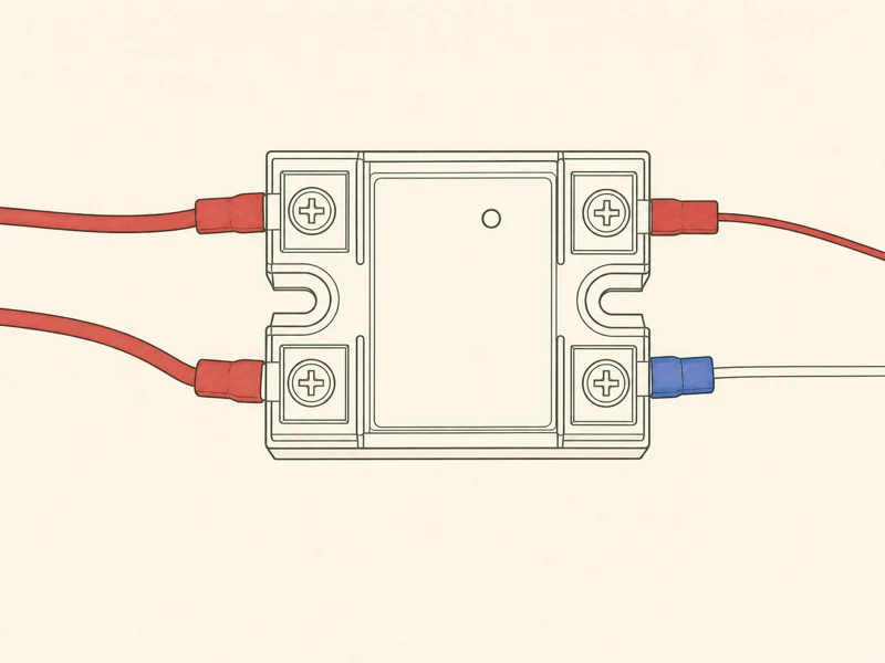
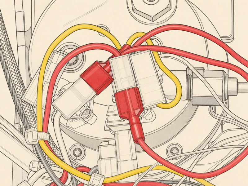
Key takeaway: Black wires handle steam, red wires handle brew; crimp, tug-test, heat-shrink every joint in that order or arcs melt insulation within a minute.
Step 12: Tap PID Main Power at the Power Switch
The PID needs 120V (or 240V, depending on your market Silvia). Auber supplies a piggyback spade connector that taps off the main power switch's black wire. Polarity matters here — black to line, white to neutral. Reverse them and the PID chassis floats at line potential, which will bite you the first time you touch the case and a grounded appliance at the same time.
The piggyback slides under the existing factory spade on the power switch, so the original load stays powered and the PID draws in parallel. Don't solder. Don't twist-and-tape. Use the supplied connector. If the factory spade is loose on the switch terminal, crimp a new female spade on the piggyback and land it on a fresh terminal — loose spades arc and burn the switch contact.
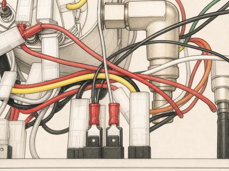
Key takeaway: Piggyback on the power switch black (line) and white (neutral); reversing them floats the PID housing at line potential and bites on first grounded touch.
Step 13: Route Wires Through the Rubber Grommet
Every wire going to the PID control box — RTD leads, SSR control leads, main power tap — passes through the rubber grommet on the back panel. That grommet is your splash seal. Without it, steam condensate and cleaning water run straight down the wiring chase into the pump compartment.
Lubricate the wires with a drop of dish soap if they bind going through. Don't force a dry bundle — the grommet tears and you lose the seal. Leave a service loop inside the chassis, four inches or so, so you can pull the PID box out to read the terminals without disconnecting anything. The first time you tune parameters you'll thank yourself for that loop.
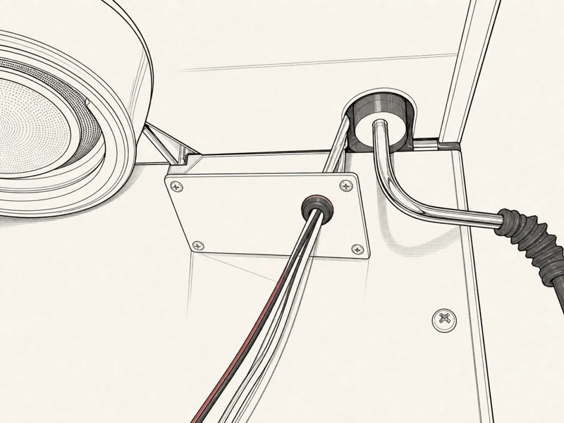
Key takeaway: Every PID-bound wire passes through that rubber grommet; soap the bundle if it binds, leave a four-inch service loop for tuning access later.
Step 14: Land the PID Terminals
The Auber terminal block is numbered. Get the order right or the PID behaves like a random number generator. Terminal 1 and 2 — main power in (line on 1, neutral on 2). Terminal 2 and 4 — bridge the brew pump jumper; this lets the PID's pre-infusion timer control the pump directly. Terminal 7 and 8 — RTD analog signal, polarity insensitive but keep it consistent. Terminal 9 and 10 — control output to the SSR.
Land them in that order, snug the screws, and tug-test every wire. A loose terminal 9 gives you a dead cold machine with no error code, and you'll spend an hour chasing the RTD and the SSR before you realize the control signal never left the PID.
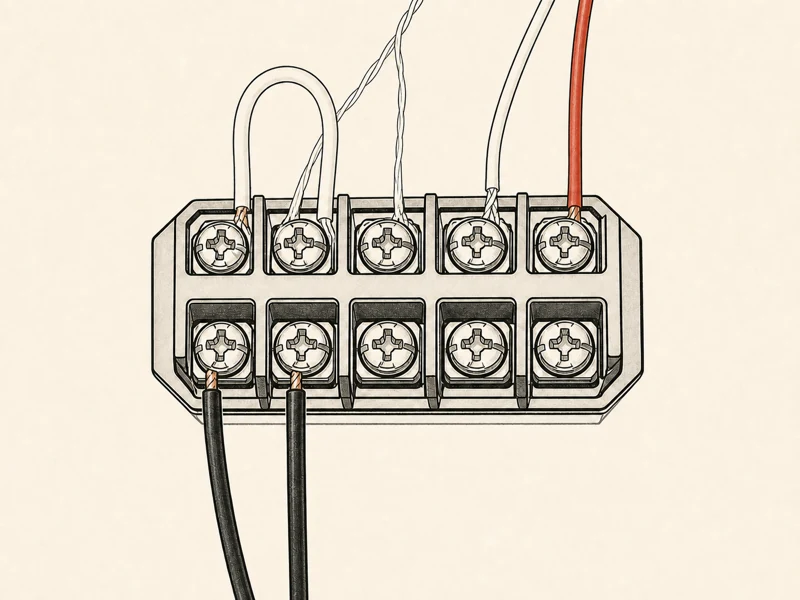
Key takeaway: Land terminals in order — 1/2 main power, 2/4 brew pump jumper, 7/8 RTD, 9/10 SSR control; tug-test every screw or chase a dead-cold machine for an hour.
Step 15: Reinstall the Top Cover and Rear Baffle
Reverse the teardown. Rear baffle first, two screws. Top cover drops back over the steam wand and water spout — flex the grommets with a fingertip to guide the pipes through. Four top screws, snug by hand. Do not overtighten; the threads go into sheet metal and will strip if you lean on the hex key.
Before you button it up, do one last visual sweep. No pinched wires between the boiler shell and the chassis wall. No RTD lead touching the element pins. No loose spade connectors. No hardware dropped into the pump compartment — a stray washer inside the chassis will rattle loose on the first shot and short something. Shine a flashlight in and look twice.
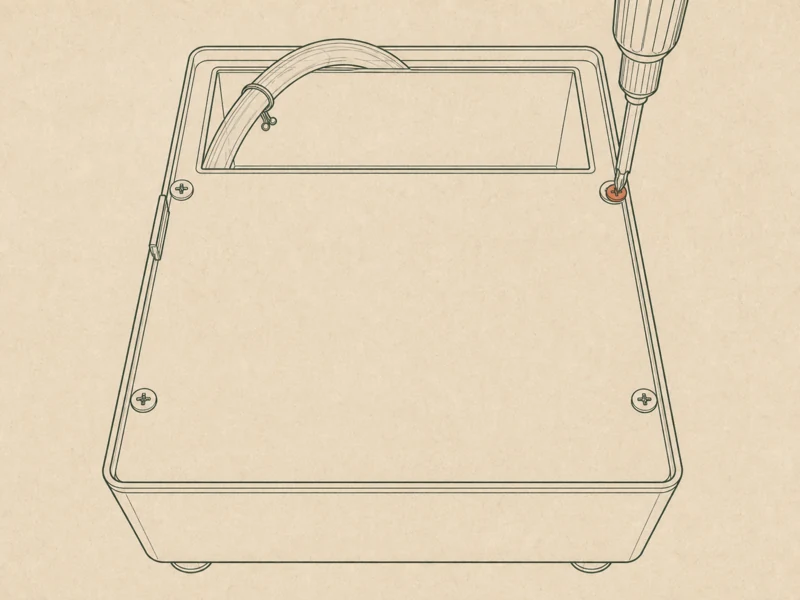
Key takeaway: Reverse your teardown, sweep for pinched wires and dropped hardware before buttoning up; a stray washer rattling loose on shot one will short something.
Step 16: First Power-On — Sensor and SSR Sanity Check
Plug in. Flip the main switch. The PID should light up and show a temperature reading within five seconds. If it reads "OPEN" or scrolls an ohms error, you have a broken RTD lead or a loose terminal 7 or 8. Power down and re-seat before going further.
If the temperature reading climbs past 110°C with the element supposedly off, kill power at the wall immediately. The SSR has failed shorted closed, and the relocated mechanical thermostat you installed in Step 6 is now your last line of defense before the boiler runs dry. A healthy first boot: PID reads 20–25°C ambient, the element kicks in within 30 seconds, and the temperature starts rising smoothly toward SV.
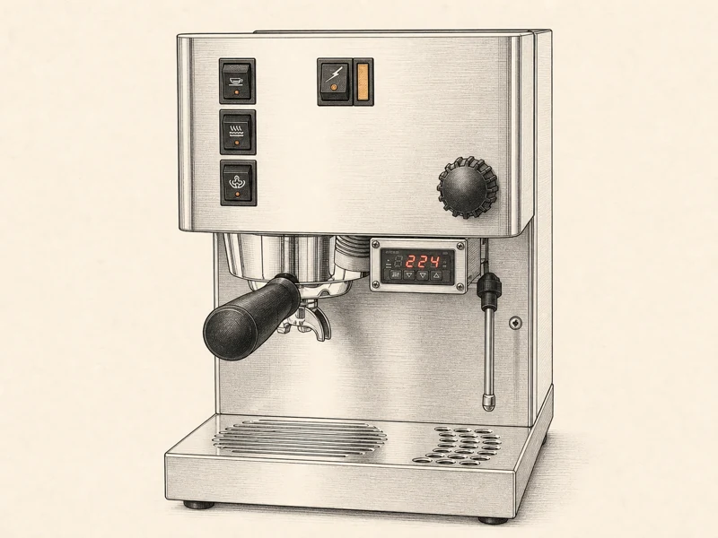
Key takeaway: PID lights in five seconds, reads 20-25°C ambient, element kicks within 30 seconds; if temp climbs past 110°C with element off, kill power at your wall.
Step 17: Set SV, P, Tp, Td, and Tb Parameters
Hold SET to enter the parameter menu. SV first — set to 228–229°F. The thermowell reads about 3.5°F lower than the actual boiler top temperature, so this compensation lands real brew water at 93°C. Set it and move on; SV is the easy one.
Then P (proportional): 1.8–3.5. Start at 2.5. Too low speeds up post-shot recovery but invites oscillation around the setpoint — the temperature will hunt ±2°C forever. Too high and the element never reaches full power, so recovery after a shot takes 90 seconds instead of 30.
Tp (pulse injection): 0.7s for a single shot, 1.2s for a double. This is the brief low-pressure wetting pulse the PID fires before the pump hits full power — it pre-wets the puck so the first high-pressure hit doesn't channel. Td (soak rest): 2.5s. Pump off, capillary action pulls the pulse water into the mid and lower puck. Tb (full extraction): 25s at 9 Bar. These are starting points; the deep guide has the full parameter table. Dial P in over your first ten shots.
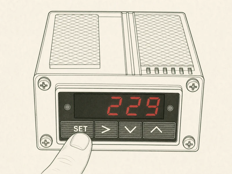
Key takeaway: SV 228-229°F, P 1.8-3.5 (start 2.5), Tp 0.7s single or 1.2s double, Td 2.5s, Tb 25s; dial P in over your next ten shots.
Step 18: First Pull and Stability Verification
Lock the portafilter, hit brew. The PID should now run the full sequence: Tp pulse (0.7s or 1.2s) → Td rest (2.5s) → Tb full pump (25s). Watch the temperature readout during the shot. A healthy install holds within ±1°C the entire pull.
If the readout drops more than 3°C during the shot, your P is too low or the RTD isn't fully seated in the thermowell — pull the cover and push the probe to the bottom of the well. If it overshoots by 5°C or more after the shot, P is too high; drop it by 0.5 and pull again. Pull three shots back to back. The temperature curve should be identical on all three. If it wanders between pulls, you have a loose terminal or a dying RTD, not a tuning problem.
Once the curve is repeatable, you're done. Go make coffee. The first shot that tastes the same as the one you pulled yesterday — that's the mod paying for itself.
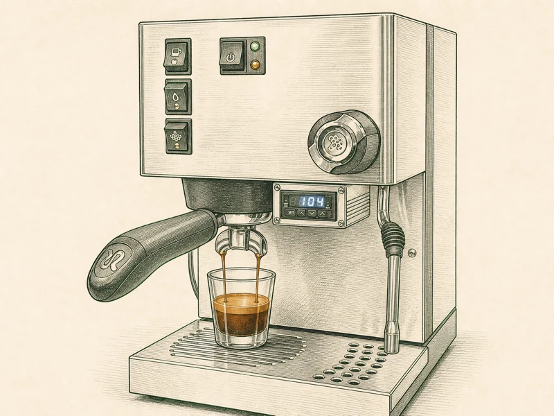
Key takeaway: Three back-to-back shots, identical temperature curves, ±1°C during the pull; wander between pulls means a loose terminal or dying RTD, not a tuning problem.
Related guides
Frequently asked questions
Can I install an Auber PID on any Silvia version?
Most Silvia versions from 2000 onward accept the Auber SYL-1512A kit cleanly. Pre-2014 machines need a careful look at the heating element pin boots — a decade of 120°C cycles turns that plastic to crumble, and a disintegrated boot leaves a bare pin bouncing inside your chassis. Post-2014 Silvias (V6 forward) ship with different power switch wiring; double-check the piggyback landing against your kit diagram before you commit. Boiler top, thermowell spacing, and pump panel hole are unchanged across versions, so the mechanical install steps translate directly. If your Silvia has an electronic brain already (rare on home models), stop and email Auber with a photo of your chassis before ordering — some grey-market imports share the Silvia badge but run different control boards.
What’s the best PID temp for Silvia?
Set SV to 228-229°F on the Auber. The thermowell reads about 3.5°F lower than actual boiler top temperature, so this compensation lands real brew water at 93°C, that classic Italian espresso target. Try 225°F for darker roasts where you want less bite; push toward 231°F for light roasts needing heat for clean extraction. Steam sits on its own mechanical stat still, so leave it alone. Don’t chase a single magic number: dial P in over ten shots, watch your temperature curve during each pull, and let taste confirm. Most of us land at 228°F and never touch it again.
How do I know if my RTD is working?
Meter your PT100M leads before seating the probe: 100-140 ohms at room temp is healthy, with 108-115 ohms typical at 20°C shop temp. Open line or a dead short means the platinum filament is broken — do not install it, call Auber for a replacement, they ship fast. After landing terminals 7 and 8, your PID readout on initial power-on is the verdict: a stable 20-25°C ambient reading within five seconds means sensor and signal path are good. An “OPEN” error or a scrolling ohms fault says you have a broken lead, a loose terminal, or a cracked element. Treat that probe like a filament bulb: grip its sheath, never the wire, because hair-thin leads have zero strain relief and snap from torsion.
What if my PID temperature keeps climbing past setpoint?
Kill power at the wall. Temperatures climbing past 110°C with element supposedly off mean your SSR has failed shorted closed — that documented failure mode of every solid-state relay. That relocated mechanical thermostat from Step 6 is your last line of defense before your boiler runs dry and the element burns through its shell. Pull your PID, disconnect SSR control leads, and meter output terminals with the PID off: zero ohms means shorted, replace that relay. Auber’s SSR-25DA is cheap and replaceable in ten minutes. Don’t try riding it out with your front switch — some kits leave PID power energized even when that front switch is off, so the only safe kill is your wall plug.
How tight should the SSR mounting screws be?
Snug by hand, then a quarter turn with a driver. Do not crank it. The SSR housing is cast aluminum and cracks under over-torque, and a cracked housing lifts its base off that heatsink pad, recreating your thermal problem. That thermal grease film between SSR base and chassis is your only thermal path — pea-sized, spread thin with a credit card or a spudger flat. Too much grease pumps out over thermal cycles and leaves an air gap, which is an insulator. Without good contact, your SSR hits its internal thermal cut within 30-60 minutes of continuous duty and drops that heating element offline mid-shot. Torque to snug, not spec.
Where this guide draws from
This walk-through follows the standard Silvia Auber PID install sequence. For the official kit manual and spec sheet, see Auber Instruments (external, opens in a new tab).
PID in? Pull the first shot.
Set 228-229°F, let it stabilize, pull a shot, read it, adjust. The deep guide has the full PID parameter table. Stuck on a step or unsure about a wiring call? Talk to us — we’ve been inside more Silvias than we care to count.
Kit installed? Pull the first shot.
Set a starting temperature, pull a shot, read it, adjust. If you're stuck, talk to us about your install.
 English
  Italiano
  Deutsch
  Español
  Français
  العربية
  日本語
日本語  한국어
한국어  香港中文
香港中文  Nederlands
  Português