
Gaggia Classic Pro / Evo Pro PID install, step by step
A full walk-through of installing a PID kit on a Gaggia Classic Pro or Evo Pro. Mains voltage inside; read the safety block first.
Prerequisites & tools
- Tools: multi-bit screwdriver, 17mm wrench, wire strippers, multimeter, crimp tool.
- In the kit: PID controller + enclosure, SSR(s), brew temperature sensor, wiring harness, zip ties, heat-shrink.
You install a PID on a Gaggia Classic Pro or Evo Pro by swapping out the brew thermostat for an RTD sensor, mounting two solid-state relays, and wiring a controller to mains. Stock thermostat swings 20°F wide; a PID tightens that to ±1°C.
Installing a PID on a Gaggia Classic Pro or Evo Pro takes 2-3 hours: unplug, strip your case, remove your brew thermostat, thread an RTD sensor into a boiler port, mount an SSR-DA for brew and SSR-AA for steam, tap neutral and hot off your rocker switch, wire up the controller, bench-test, button it up. Same boiler, same case — switch wiring branches by model.
Twenty-eight steps, eighty-four photos, every screw and terminal called out. Read every safety block twice. Follow the order. By Step 32 you'll have a machine that holds temperature like a commercial unit.
Step 1: Overview
This covers a PID install on both the Gaggia Classic Pro and the Evo Pro. Same aluminum boiler, same stamped steel case, same headaches lurking inside. Every difference between those two machines lives in the rocker switch wiring — I call those out at Steps 15 and 16 where the harness branches. Read this whole guide front to back before you turn a single screw. The order exists for a reason: you pull the boiler before you touch thermostats, you wire relays before you button up the case, you bench-test before you close anything. Skip ahead and you'll find yourself disassembling work you already finished. Several steps branch by model or by kit flavor — aluminum enclosure versus 3D-printed, vent clip versus individual relays. I flag every fork where it happens.
Key takeaway: Read the full guide before starting. Same boiler and case across both machines; switch wiring branches at Steps 15-16.
Step 2: Safety & Liability
I'm not going to sugarcoat this. Mains voltage lives inside that stamped steel case, and it doesn't care about your coffee hobby. "Unplugged" means the physical cord is out of the wall — not just the rocker switched off, not "I think I flipped the right breaker." The boiler holds enough heat to blister your fingers for a solid hour after power-off. If you cannot identify hot, neutral, and ground by looking at wire colors, stop reading and pay someone who can. No PID kit is worth a house fire or a trip to the emergency room. Photograph every connector before you unplug it, and photograph it again after. Those photos are your rollback when reassembly goes sideways at 11 PM and you can't remember which spade went where. You do this work at your own risk. I've installed enough of these kits to know exactly where they bite, and I'm telling you straight: respect the mains or put the screwdriver down. For the full multimeter check procedure, see the mod safety and multimeter checks page.
Key takeaway: Cord out of the wall, not just rocker off. Boiler stays hot for an hour. Photograph every connector before and after disconnecting.
Step 4: Parts Identification
Empty the kit bag on your bench and check every piece against the list before you open the machine. You should have: PID controller with its enclosure, two solid-state relays — SSR-DA for brew, SSR-AA for steam — a threaded RTD thermocouple, and the wire bundle. That bundle contains a yellow ring-terminal wire, yellow and black piggyback spade connectors, a blue female-to-female wire, a blue jumper, two male spade PWM wires, thermal compound, two rubber grommets, zip ties, heat-shrink, spiral wrap, alcohol wipes, a hex key, and the flow control knob. Tools you bring yourself: multi-head screwdriver, 17mm wrench or an adjustable, pliers, and a multimeter. The multimeter is non-negotiable — if you don't own one, buy one before you start. You'll use it more than every other tool combined. Missing a part from the kit? Contact the vendor before proceeding. A kit shipped short on heat-shrink or missing a grommet turns a three-hour install into a three-day wait.
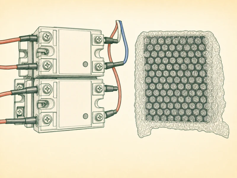
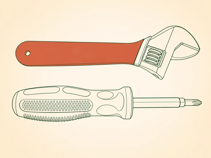
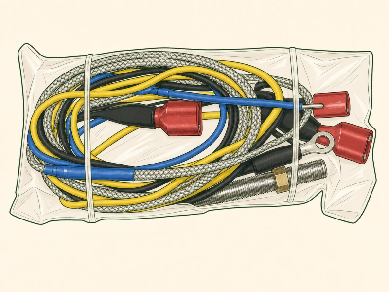
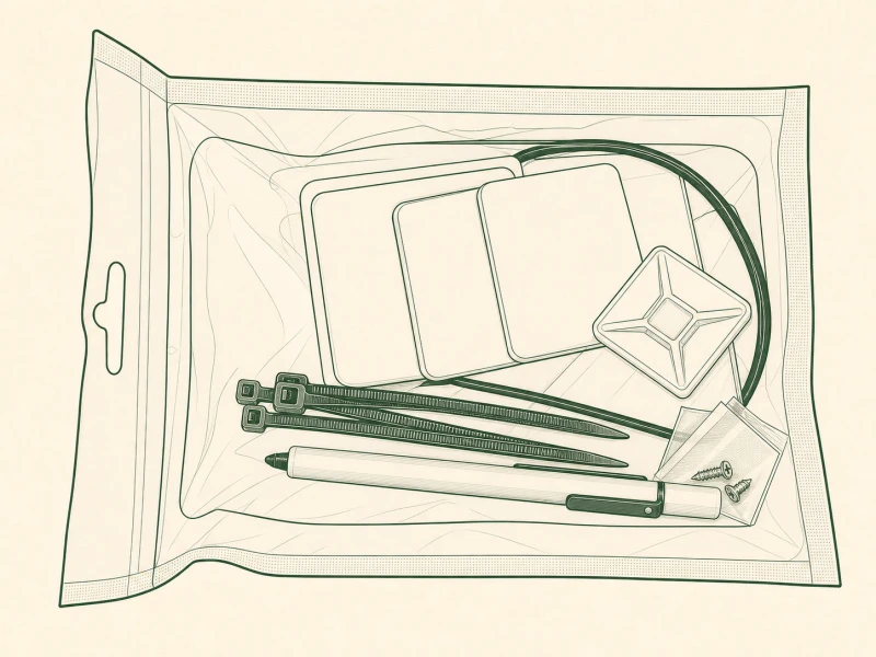
Key takeaway: Verify all parts against the list before opening the machine: two SSRs (DA brew, AA steam), RTD thermocouple, full wire bundle, thermal compound, grommets. Bring your own multimeter.
Step 5: Before We Begin
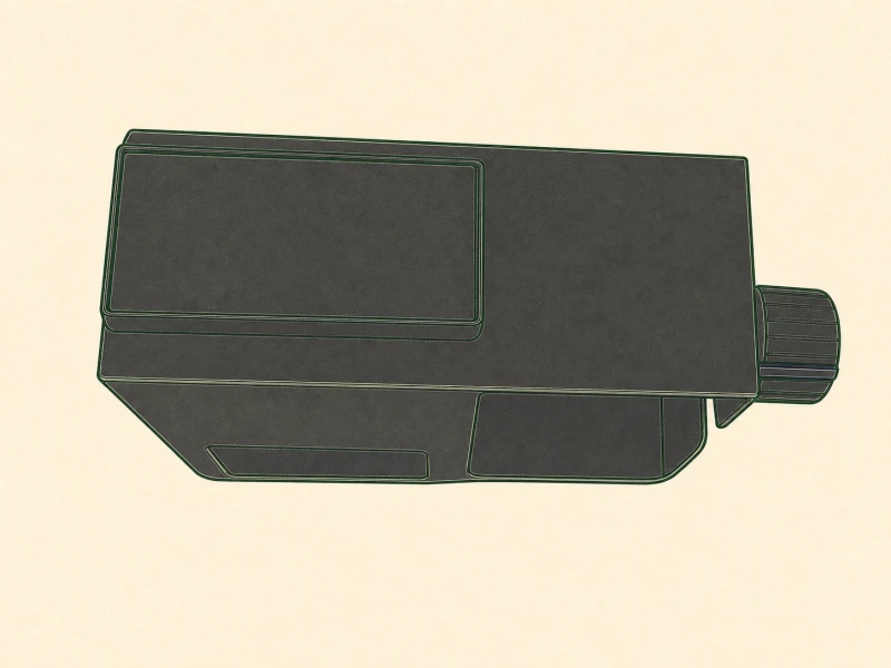
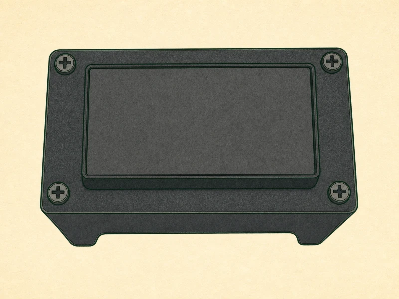
Two enclosure flavors ship with this kit: aluminum and 3D-printed PLA. The rest of this guide walks the aluminum path because it's the original design and the one most kits still ship. The wiring harness, relay placement, and controller terminal mapping are identical between the two — only the physical mounting differs. If your kit arrived with the 3D-printed enclosure, follow along for every electrical step, then adapt the mounting holes to suit your plastic shell. The 3D-printed version uses self-tapping screws into plastic bosses where the aluminum uses machine screws into threaded posts. Don't mix the two. If you try to force a machine screw into a plastic boss, you'll strip it and have nothing to bite on. Check which enclosure you have before Step 6 so you're not mid-disassembly trying to figure out where the controller mounts.
Key takeaway: Aluminum and 3D-printed enclosures share identical wiring; only mounting differs. Confirm which you have before Step 6.
Step 6: First Steps (Aluminum Enclosure Guide)
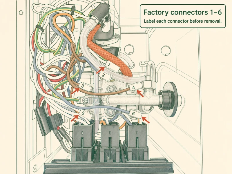
Strip the machine down before you open the case. Remove the portafilter, drip tray, solenoid blowoff tube if yours has one, and the water tank. Set them aside in order so reassembly is muscle memory, not archaeology. Before you unplug any internal connector — and I mean every single one — photograph it in place and tape-number both halves with a small label. Connector 1 to connector 1, connector 2 to connector 2. Those numbers and photos are the only thing standing between you and a two-hour guessing game on reassembly day. I've watched builders skip this step, confident they'll remember, then stare at a harness of identical black spade connectors at midnight wondering which went to the pump and which went to a thermostat. Tape and a Sharpie cost two dollars. Use them. While the case is open, eyeball every wire for heat damage, cracked insulation, or corroded spades. An older Gaggia may need connector replacement before you add a PID to the mix.
Key takeaway: Strip the machine fully, then photograph and tape-number every connector before disconnecting. Heat-damaged wires need replacing before PID install.
Step 7: Remove the Steam Valve
Skip this step entirely if you're only doing the flow-control dimmer upgrade — the steam valve can stay put. For a full PID install, you need the wand out of the way before the boiler moves. Grab pliers and crack the nut next to connector #4 on the boiler. That nut is the steam wand union, and it's been heat-cycled a few thousand times, so it may fight you. Once it breaks loose, back the wand down and out of the way. You're clearing room for the boiler lift and thermostat access coming up in Steps 8 and 12. Don't remove the wand completely from the machine unless you want to re-plumb the whole steam path — just get it clear of the boiler body. If the nut is corroded and won't budge, a drop of penetrating oil and five minutes of patience beats a stripped fitting and a parts order.
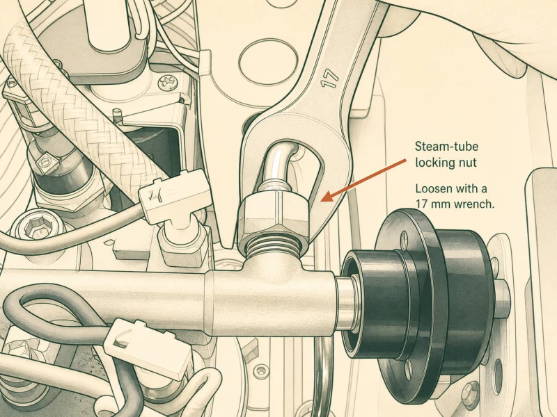
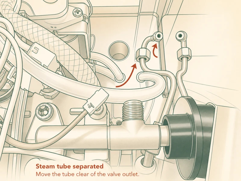
Key takeaway: Crack the nut at connector #4 (steam wand union) with pliers. Skip this step if only doing flow-control.
Step 8: Loosening the Boiler
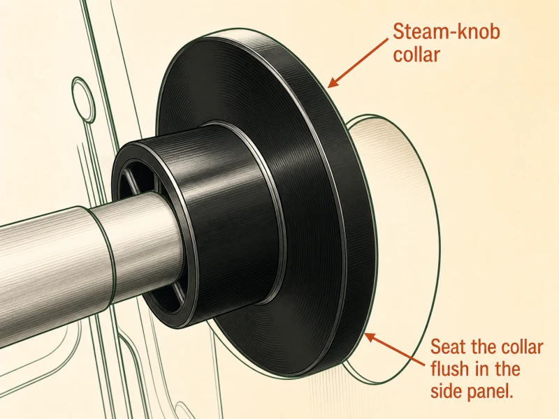
Same skip condition as Step 7 — flow-control-only builds don't need boiler removal. Everyone else: four hex-head bolts hold the boiler assembly to the stamped case. They're on the outside of the chassis, arranged around the portafilter boss. Back all four out with your hex key. Once the last bolt clears, the boiler and grouphead assembly lifts free of the housing. With the boiler loose, the steam knob collar pulls straight up and off through the hole in the top cover. Set the bolts somewhere magnetic — they're a specific length and thread pitch, and losing one means a hardware store trip that wastes an hour. Support the boiler from underneath as you free the last bolt. Aluminum boilers dent and crack if dropped, and a cracked boiler is a write-off, not a repair. Once the boiler is free, you have working room for every step that follows.
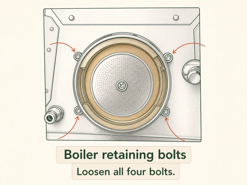
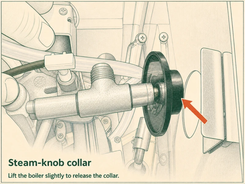
Key takeaway: Four hex-head bolts around the portafilter boss. Back them out, lift the boiler free, pull the steam knob collar up through the hole.
Step 9: Remove the Power Cable Entrance Fitting
Check your power cable before you touch this fitting. Two-prong cable machines don't need this step — skip it and move to Step 10. Three-prong machines need the entrance fitting pulled to get working room for the pump connector. Before you depress a single tab, photograph the fitting from inside the case. Which wire goes to which prong matters — get the photo, label the wires if the colors aren't obvious. Four plastic tabs hold the fitting in the case back. Depress all four simultaneously — easier with two hands or a flathead levering each pair — and the fitting pops out the rear. Don't force it; if a tab won't depress, look for a molding flash or paint lock holding it. The fitting is plastic and the tabs snap off if you lever too hard. Set the fitting aside with its wires still attached to the harness. You'll re-seat it at Step 18.
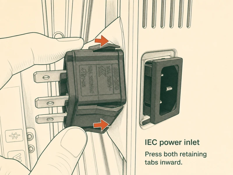
Key takeaway: Two-prong machines skip this. Three-prong: photo the fitting before anything else, depress four plastic tabs, fitting pops out the back.
Step 10: Disconnect the Brew Pump Connector
Two wires run to the brew pump: a thin signal wire and a thicker gray power wire. You're disconnecting the thick gray one — that's the feed we tap for the flow-control dimmer in the next step. Squeeze the spade connector and pull it straight off the pump tab. Don't yank sideways; the tab is soldered to the pump body and a sideways pull can crack the solder joint. If access is tight, shove the pump assembly aside gently to get your hand in. The pump is rubber-mounted, so it has some give. Note which tab the gray wire came from — you'll need that tab free for the blue female wire in Step 11. Leave the thin wire connected. It handles the pump's startup signal and doesn't factor into the dimmer circuit. For pump fault diagnosis after install, check the Gaggia fault diagnosis page.
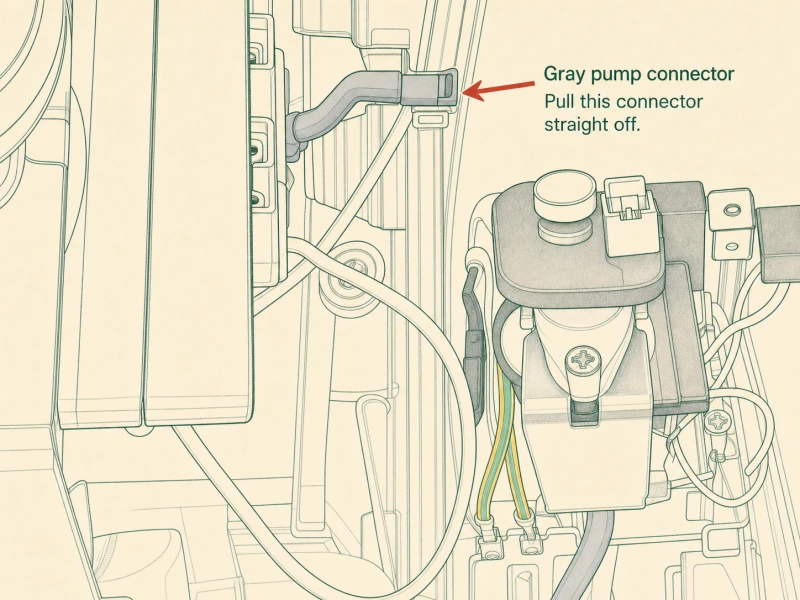
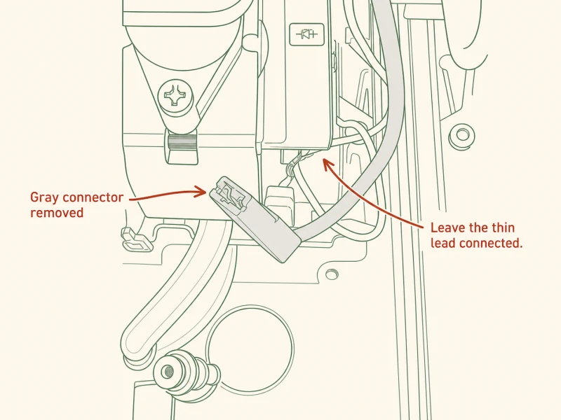
Key takeaway: Disconnect the thick gray power wire from the brew pump tab. Leave the thin signal wire connected. Note which tab is now free.
Step 11: Connect the Water Flow Control Switch
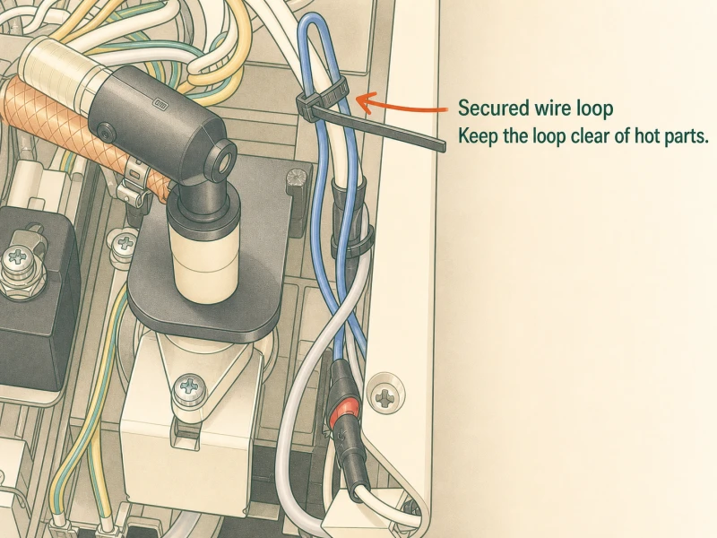
Grab the shorter blue female wire from the kit and push it onto the pump tab you just freed. It should seat with a click — if it slides on without resistance, check that the locking tab on the connector isn't bent flat. Next, feed the dimmer's two wires through the leftmost vent slot in the case. Grommet goes in before the wires — lever it into the vent slot with your flathead if the rubber fights you. A properly seated grommet keeps vibration from chafing the wire insulation against the steel edge. Route the dimmer wires inside the case and mate their male spade ends to the blue female wire. Zip-tie the slack so nothing dangles into the boiler or pump. Wipe the case where the dimmer will stick with an alcohol pad, let it flash off, then peel and stick the dimmer pad. A greasy case means the adhesive lets go in a week. Clean metal means it stays put for years.
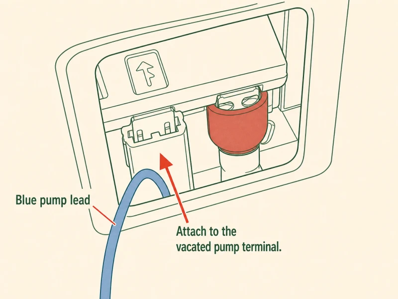
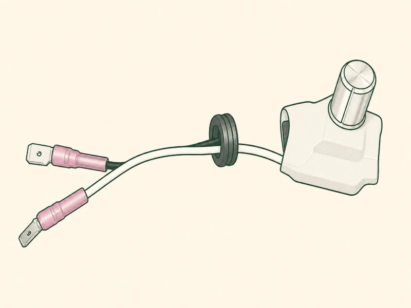
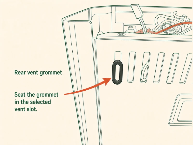
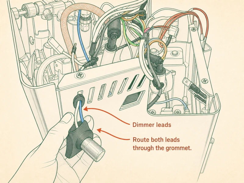
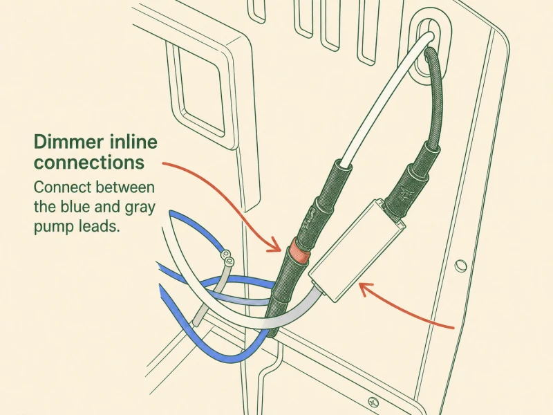
Key takeaway: Blue female wire onto freed pump tab. Grommet into leftmost vent slot before the wires, then dimmer wires through. Alcohol-wipe the case before sticking the dimmer.
Step 12: Remove the Brew Thermostat
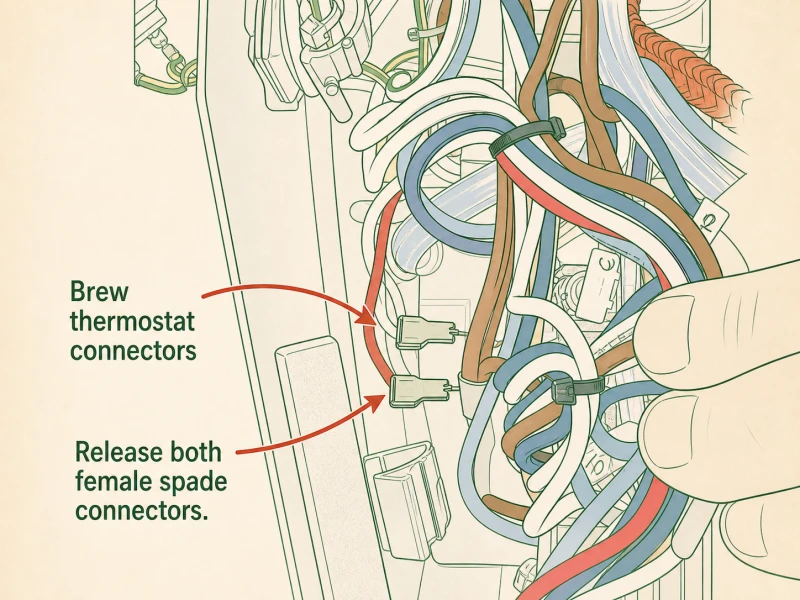
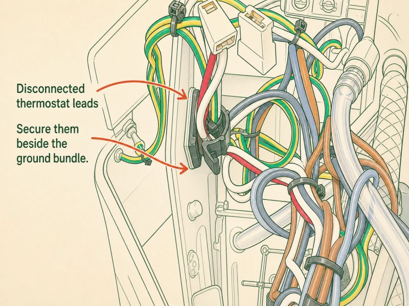
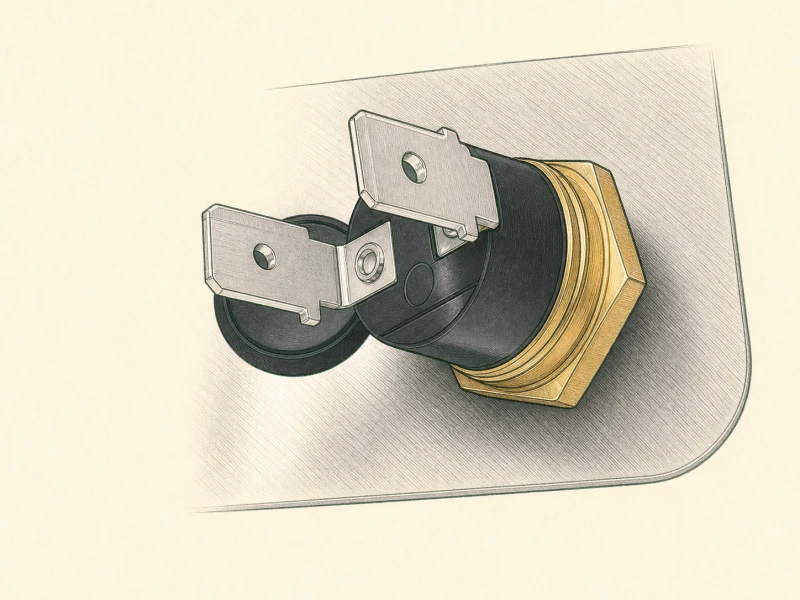
Two thermostats sit on the boiler: the top one handles steam, the side one handles brew. You're pulling the side one — it's the bimetal switch the PID replaces. Lift the boiler and grouphead assembly up out of the case and set it inside the chassis so you have clear access to the side thermostat. Take your flathead and lever the two spade leads off the thermostat terminals gently. Don't yank the wires — the spades grip tight, and a hard pull rips the crimp off the wire or snaps the terminal post. Lever under the spade edge and rock it off. Once both leads are free, tuck them up into the ground clip alongside the green/yellow wires — they'll stay live and need insulation. Now unscrew the brew thermostat from the boiler. It's a standard thread; turn it counterclockwise and it backs out. You won't need it again. The steam thermostat stays put unless you're doing the steam relay upgrade in Step 20.
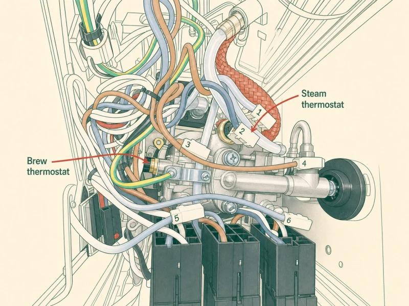
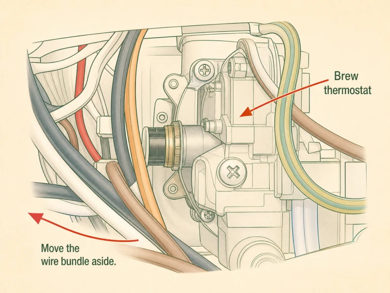
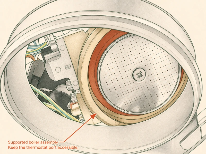
Key takeaway: Top thermostat = steam (leave it), side = brew (pull it). Lever spade leads off gently, tuck into ground clip, unscrew the brew thermostat.
Step 13: Install the New Brew Sensor
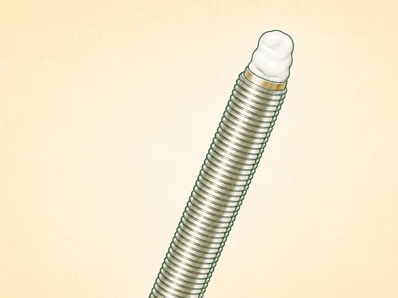
Grab the threaded RTD thermocouple from the kit. A tiny dab of thermal compound on the threads — and I mean tiny, a rice-grain amount. The OEM paste still coating the boiler threads from the old thermostat does most of the work. Too much compound squishes out, makes a mess, and insulates the threads from the case ground path. Slide a heat-shrink sleeve over the sensor threads before you thread it in. Use the sleeve to push the compound into the thread roots, then thread the sensor into the side of the boiler hand-tight. Don't wrench it. The brass boiler threads are soft, and the RTD body is stainless — cross-thread it and you're buying a new boiler. Once the sensor seats, drop the boiler and grouphead assembly back into the case. The sensor wire routes up toward the controller location. Keep it clear of the boiler body and the steam path — heat kills sensor wires faster than anything else in this machine.
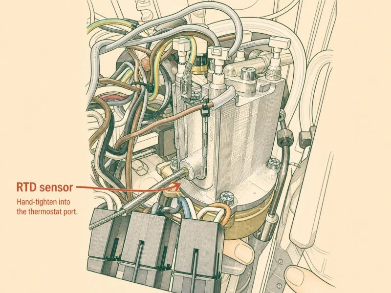
Key takeaway: Rice-grain of thermal compound on RTD threads, heat-shrink sleeve over threads, hand-tight only. Brass boiler threads strip easily.
Step 14: Adding Your Neutral Wire Tap
The PID controller needs a neutral feed, and the cleanest tap point is the rocker switch. Here's where the install branches: Evo Pro and Classic Pro route neutral differently through that switch. The Evo Pro's toggled-side neutral is accessible for a piggyback spade after a simple top-to-bottom wire swap. The Classic Pro buries the toggled-side neutral where you can't physically reach it, so you swap both sides beforehand to expose the right wire. Both approaches end at the same result: a piggyback spade on the neutral feed that powers the PID. Pick your machine and follow the matching step. If you don't know which machine you have, check the model plate on the bottom — Evo Pro says "Evo" or has a post-2023 date code. The rocker switch itself looks identical on both, so the plate is your only reliable identifier.
Key takeaway: Neutral tap branches here: Evo Pro at Step 15, Classic Pro at Step 16. Check the model plate on the machine base if unsure.
Step 15: Adding Your Neutral Wire Tap (Evo)
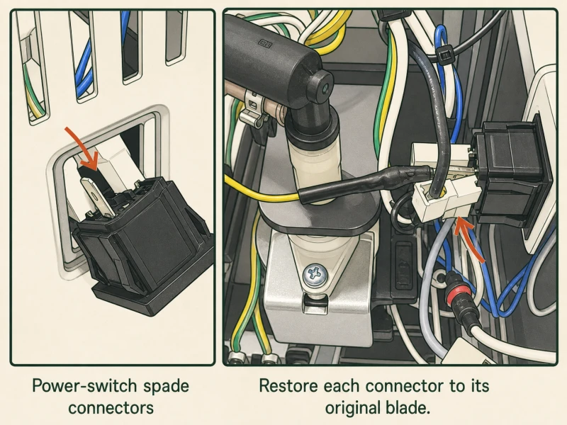
Photo the four wires on the rocker switch before you touch anything. Two on top, two on bottom, and they are not interchangeable — mix them up and the machine behaves unpredictably or trips a breaker. The female spade ends have locking tabs that grip the switch terminals. Depress the tab with a small flathead or pick and push the wire out at roughly 30 degrees — straight back won't release, and yanking breaks the tab. Swap the top-left wire to bottom-left, and the top-right to bottom-right. Now the toggled-side neutral sits where you can reach it. Add the piggyback spade connector to the wire you just moved — that spade is the PID's neutral feed. Secure the black cable end on the side alongside the other wires so nothing dangles. Double-check your photo against the current layout before you move on. If the wires don't match the photo after your swap, stop and retrace — you've crossed something.
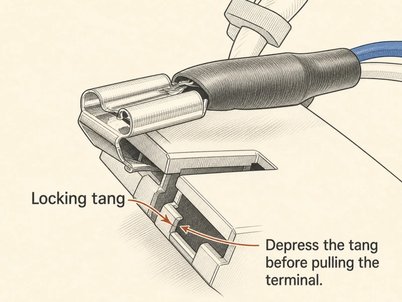
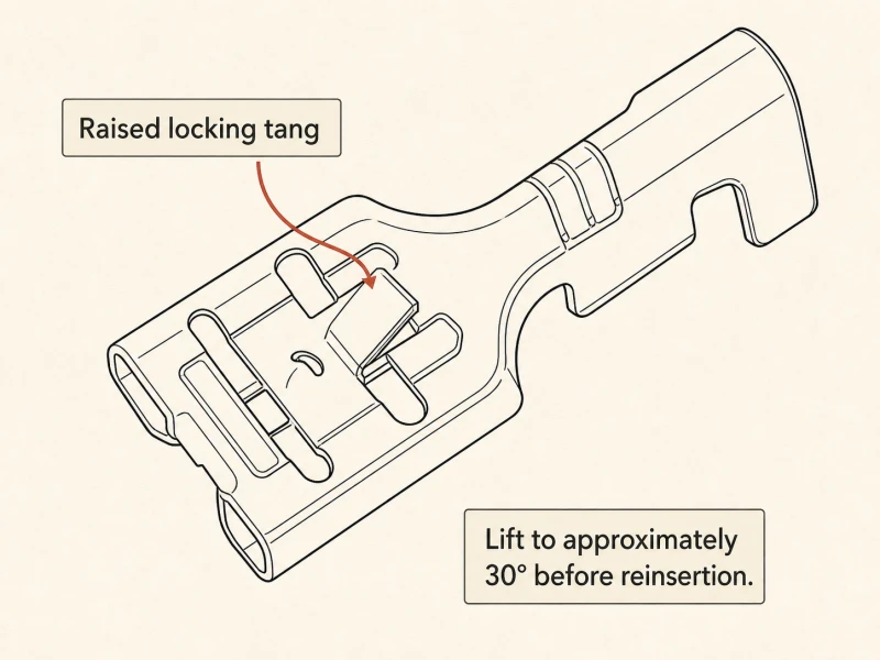
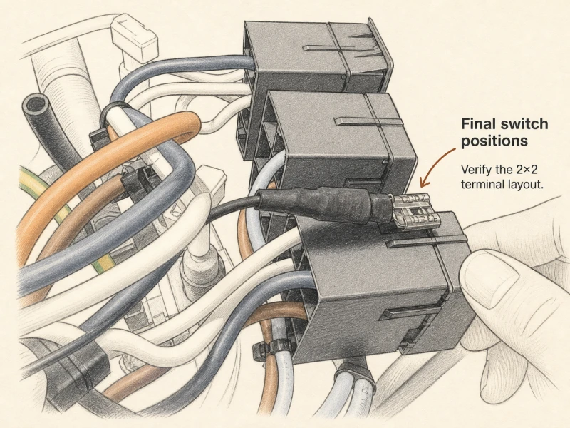
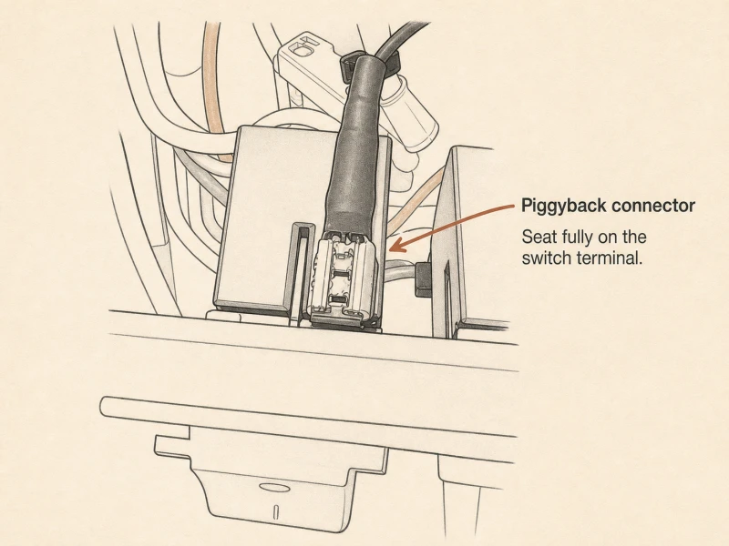
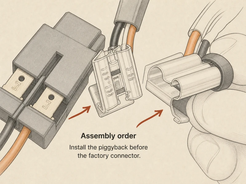
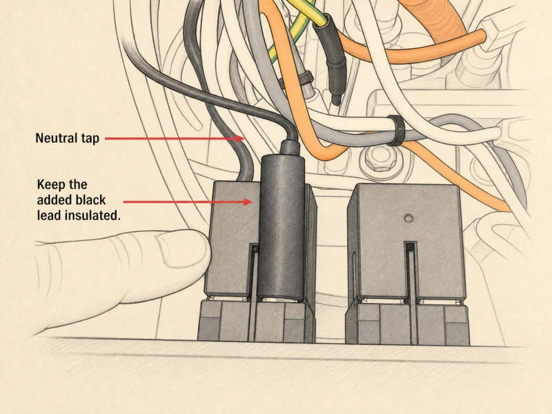
Key takeaway: Photo the four rocker switch wires before anything else. Depress locking tabs, push wires out at 30°. Swap top-to-bottom on both sides, add piggyback spade to the moved wire.
Step 16: Adding Your Neutral Wire Tap (Pro)
Same safety rules as the Evo branch — mains side, machine unplugged, photo before you start. The Classic Pro's toggled-side neutral sits buried behind the switch body where you can't physically fit a piggyback spade. So you swap beforehand to expose it. Swap top and bottom on both sides of the switch — top-left to bottom-left, top-right to bottom-right. After the swap, the wire you need (formerly bottom-right, now top-right) sits accessible. Pull that top-right connector and add the piggyback spade to it. That spade feeds neutral to the PID. The physical difference from the Evo is that the Pro's switch mounting puts the toggled terminal flush against the case wall, leaving no finger room for the spade until you've rotated the wire position. The harness length is tight on the Pro, so don't pull any more wire than you need to get the spade seated.
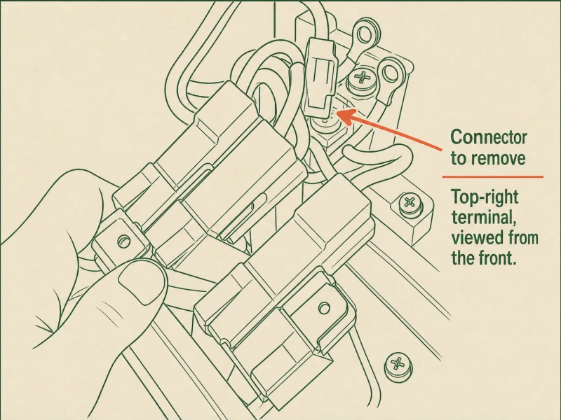
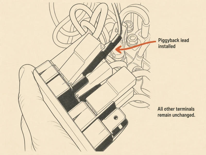
Key takeaway: Classic Pro: swap top-to-bottom on both sides beforehand, then pull the top-right (formerly bottom-right) connector for the piggyback spade. Harness is tight, don't over-pull.
Step 17: Adding Your Ground Wire
Two grounding posts sit on top of the boiler, right next to the thermal fuse. If your machine is three-prong, one post already carries a factory green/yellow ground wire — leave that one alone. The new yellow ring-terminal wire from the kit goes on the other post. Loosen the nut on the empty post, slide the ring terminal over it, and re-tighten. The ring terminal needs to sit flat against the post shoulder, not cocked sideways. A cocked ring terminal loosens under vibration and creates a high-resistance ground path — exactly the failure mode that puts live voltage on the case. If your machine is two-prong, both posts may be empty. Use one for the yellow ring-terminal now; the other gets wired in Step 29 when you do the full ground retrofit. Torque the nut by hand with a small wrench — tight enough to stay, not so tight you strip the brass post.
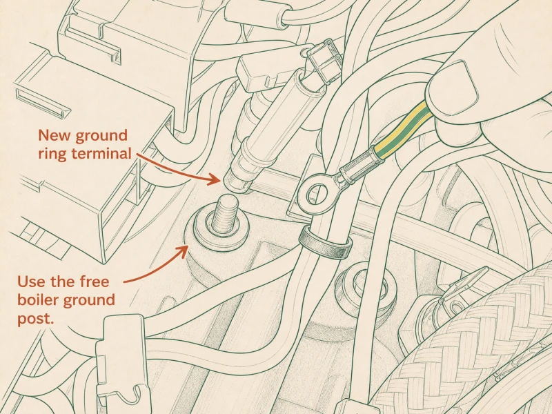
Key takeaway: Two ground posts on the boiler top. Three-prong: leave the green/yellow wire, add yellow ring-terminal to the other. Two-prong: use one post now, both at Step 29.
Step 18: Connect the Hot Wire Tap
Take the yellow piggyback wire and plug its male end into the female of the black wire you pulled from the power cable entrance. That black wire is the hot side of the mains feed — the piggyback spade on it gives you a switched-hot tap for the PID. The connection should seat with a firm click. If it slides in loose, the female connector is fatigued and needs replacing before you button up. While you're in here: if you removed the power cable entrance fitting at Step 9 to access the pump, re-seat it now. Press it back through the case back until all four plastic tabs click into place. Give it a tug to confirm it's seated — a loose fitting lets the harness shift during vibration, and a shifted harness can chafe against the boiler or case edge. Route the yellow piggyback wire up toward the controller area, keeping it away from the boiler body and the steam path.
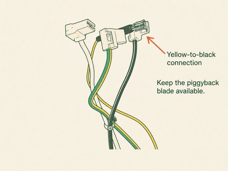
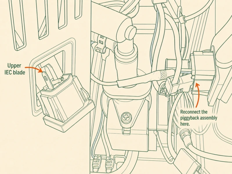
Key takeaway: Yellow piggyback male into black wire female (hot side). Re-seat the power cable entrance fitting if you pulled it at Step 9.
Step 19: Install & Mount Both Relays
Two relays, two vent holes. The steam relay — SSR-AA, identified by its blue and white wires — mounts in the far-right vent hole on the case. The brew relay — SSR-DA, identified by its two red wires — mounts in the second vent hole from the left. Smear a thin layer of thermal compound on the back of each relay before you seat it. These relays shed their heat through the case steel, and the compound fills the microscopic air gaps between the relay back and the case. Without compound, the relay overheats under sustained brew cycles and the internal triac fails. The steam relay's mounting screw shares its vent hole with the rubber grommet you installed for the flow-control wires. Put the screw below the grommet, thread the nut lightly, then angle the relay body as far right as it'll go before you snug the nut. That offset keeps the relay clear of the boiler and the wiring harness.
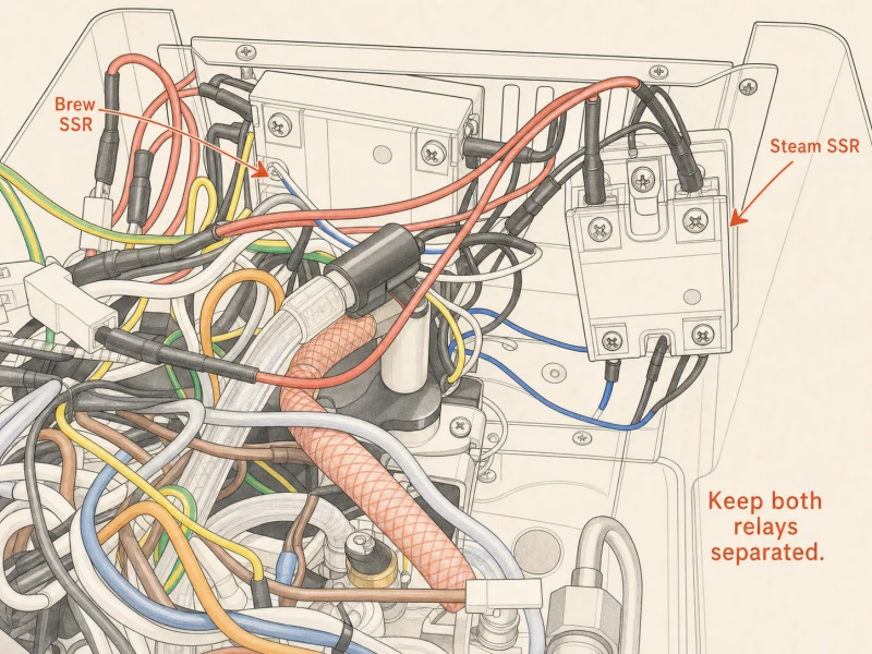
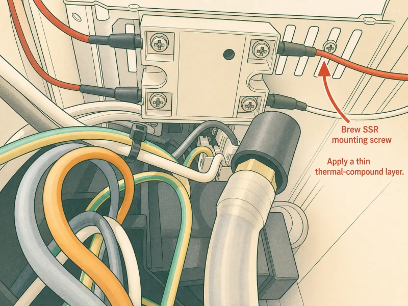
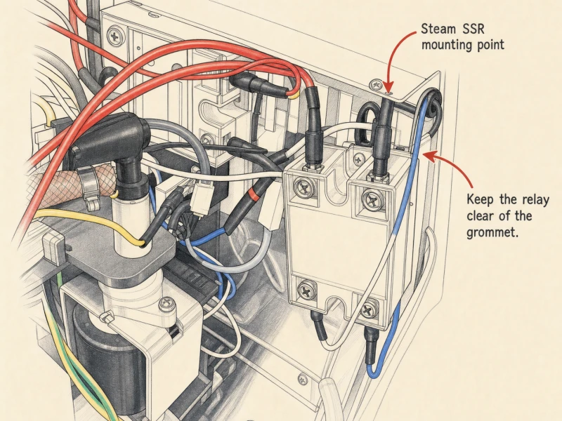
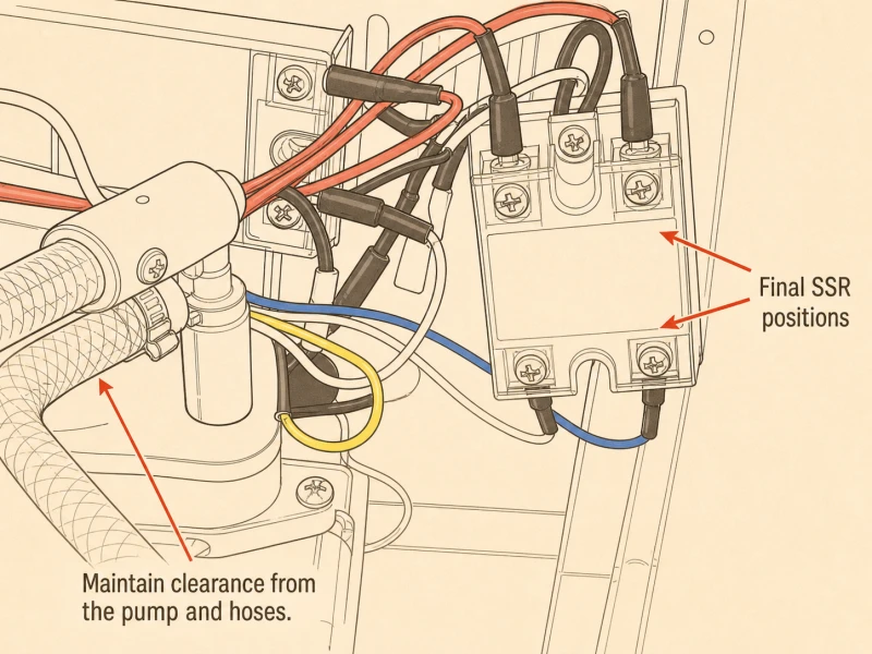
Key takeaway: SSR-AA (blue/white) far-right vent, SSR-DA (red/red) second-from-left. Thermal compound on both relay backs. Steam relay screw goes below the grommet, angled right.
Step 20: Connect the Relay Wires
Grab the two spade connectors you pulled off the brew thermostat at Step 12. Push them onto the two thick red male spades on the SSR-DA brew relay. Orientation doesn't matter — the relay switches AC, so polarity is irrelevant. Seat each connector until it clicks. Zip-tie the slack wire so nothing dangles into the boiler or pump. If you're also doing the steam relay upgrade: pull connector #1 and connector #2 off the steam thermostat (the one on top of the boiler you left alone at Step 12). Push those two connectors onto the #1 and #2 male spades on the SSR-AA steam relay. Same deal — either orientation works. Tuck the old steam thermostat up into the chassis out of the way. You don't need to remove it completely, just get it clear of the relay and boiler. The thermostat is now dead circuit — it sits in the harness doing nothing, which is fine.
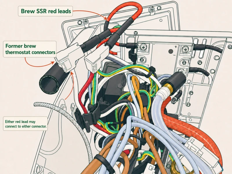
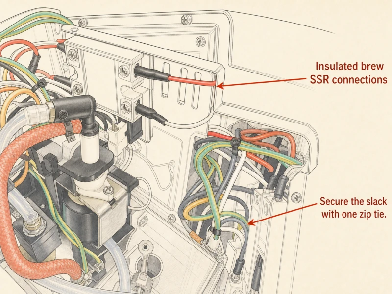
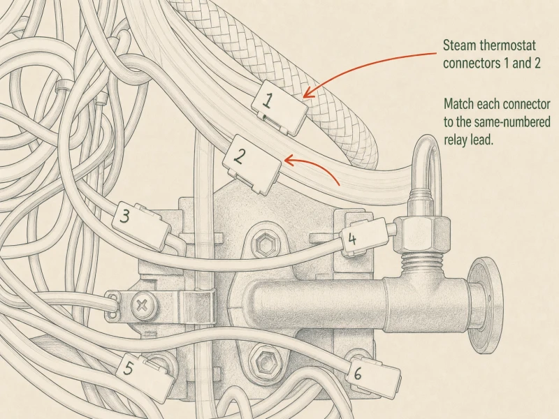
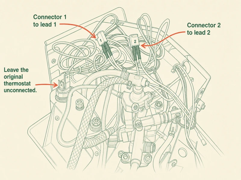
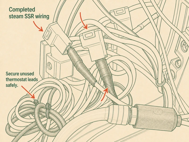
Key takeaway: Brew thermostat connectors onto SSR-DA's two red spades (either orientation). Steam upgrade: #1 and #2 connectors from steam thermostat onto SSR-AA's #1 and #2 spades.
Step 21: Feed New Wires Through Grommet
Twist the blue and white wire ends from the steam relay together — a tight hand-twist is enough, no pliers needed. Route the twisted pair through the grommet you installed back at Step 11 for the flow-control wires. If your kit shipped with the vent clip relay mount instead of individual relays, you may have a dedicated grommet for the relay wires — use that instead. Don't force wires through a grommet that's already at capacity. A crowded grommet pinches insulation, and pinched insulation chafes through against the case edge until you get a short. If the existing grommet is full, pick a different vent slot and install a second grommet there. The case has plenty of vents; use them. Route the twisted pair up toward the controller area, keeping the run as short as practical. Long wire runs pick up noise and look messy; short runs stay clean and serviceable.
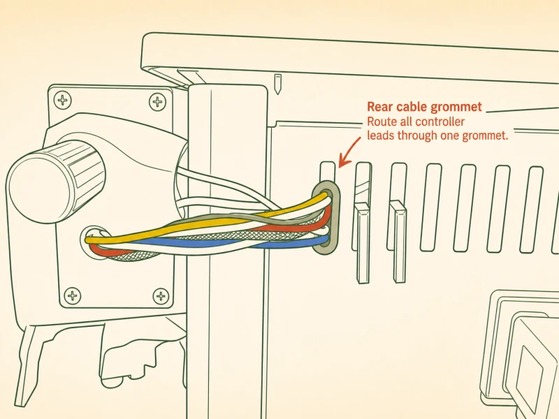
Key takeaway: Twist steam relay's blue and white wires together, route through grommet. If grommet is full, use a different vent slot — never force a crowded grommet.
Step 22: Connecting Wires to the Controller
Loosen every terminal on the back of the PID controller except terminal #3. Leave #3 alone — it's not used in this kit. Wire it up in this order: black wire to terminal #2 (rocker neutral feed), yellow wire to terminal #1 (switched hot). Brew relay: white wire to #9 (SSR negative), red wire to #10 (SSR positive). Steam relay: blue wire to #5, white wire to #2 alongside the black neutral. Three thermocouple wires go to their dedicated sensor pins — whichever color you have only one of goes to its own pin, and the two same-color wires go to the other two pins. Your kit wiring card has the exact color-to-pin pair; match it precisely. Finally, the blue jumper wire goes from terminal #4 to terminal #1. After the jumper, terminal #1 carries two wires: the yellow switched-hot and the blue jumper. Triple-check every terminal against the kit wiring card before you plug the machine in. A wrong pin here lets smoke out of the controller, and that smoke is non-refundable.
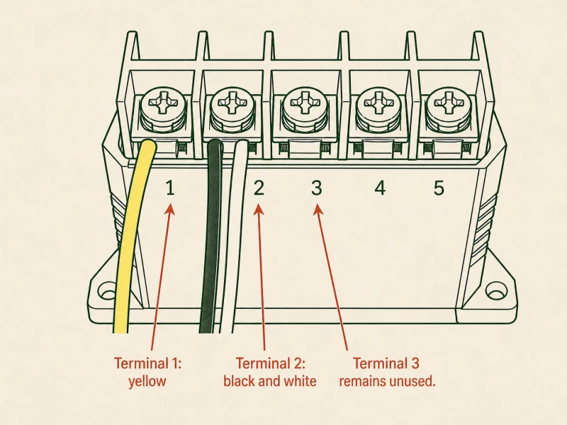
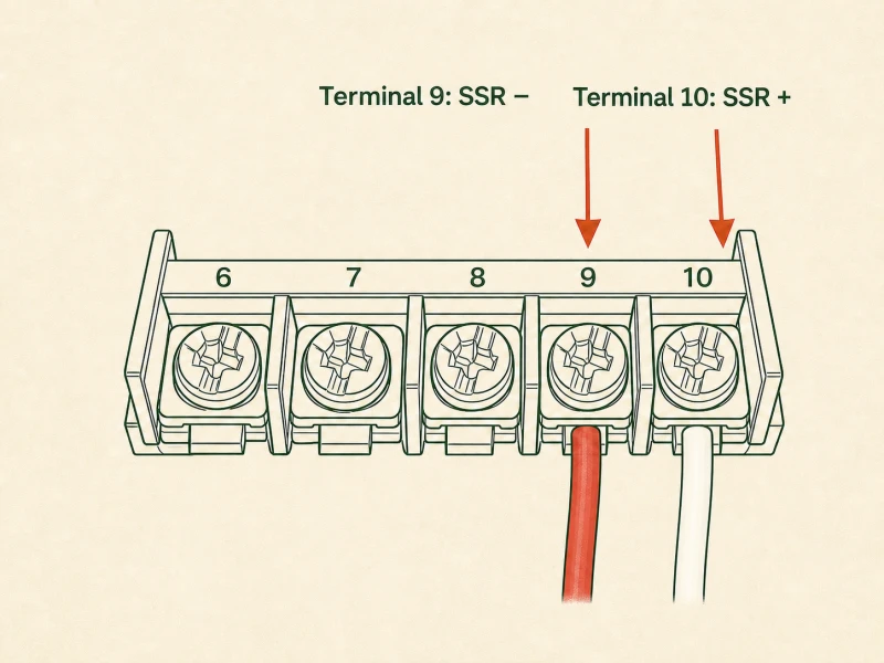
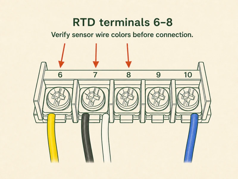
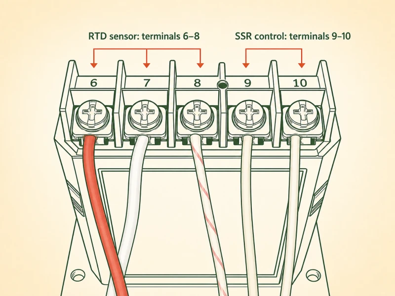
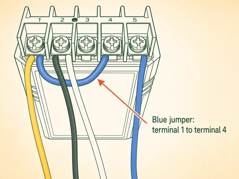
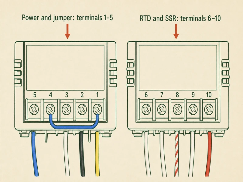
Key takeaway: Terminal map: #2 black neutral, #1 yellow hot + blue jumper from #4, #9/#10 brew relay (white/red), #5/#2 steam relay (blue/white), three thermocouple wires per kit card. Leave #3 alone.
Step 23: Putting the Machine Back Together
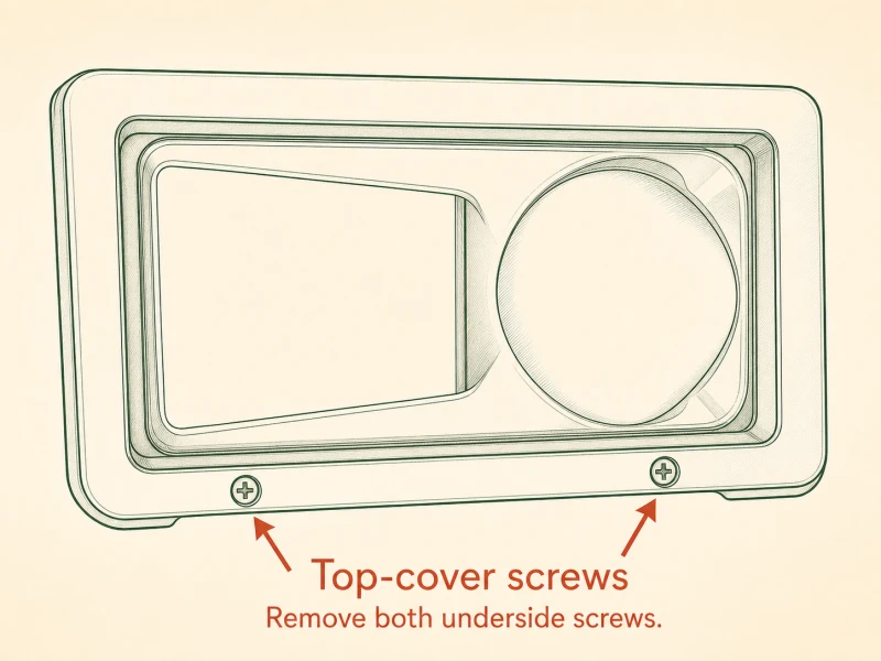
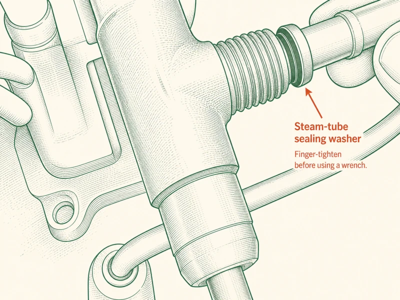
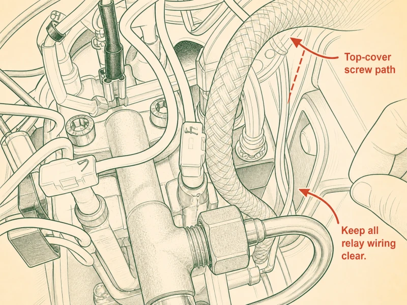
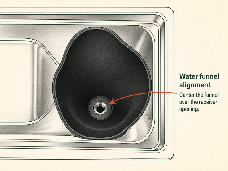
Before you close anything, disconnect the red wire from PID terminal #10 and slip the included cable jacket over the bare end. That bare wire can short to the chassis during the bench test — the jacket insulates it until final assembly. Drop the boiler and grouphead assembly back into the case and finger-tighten the four hex-head bolts you pulled at Step 8. Don't wrench them yet — you may need to shift the boiler for relay wire routing. Steam wand goes back next: finger-tighten the locking nut onto the boiler union, then snug it with pliers. A quarter-turn past finger-tight is enough; overtighten and you deform the union washer. Top cover goes on last. Before you run the screws, check that the steam relay and its wires are clear of the screw holes — a screw through a relay wire is a dead short. Line up the water funnel hole with the reservoir fitting, then run the two top cover screws.
Key takeaway: Jacket the bare #10 wire before bench test. Boiler bolts finger-tight. Steam nut quarter-turn past finger-tight. Check relay wires clear of cover screws before closing.
Step 24: Configuring the PID Controller
Bench test before you button up. Take the ring-terminal end of the yellow ground wire — the other end is already on the boiler ground post from Step 17 — and screw it to any of the eight holes on the PID enclosure. This is a temporary ground for the enclosure metal during testing; you'll move it to its permanent spot at Step 25. Plug the power cable into the back of the machine and into the wall. Keep one hand on the plug. If anything smells wrong, if the PID stays dark, if you hear a buzz that wasn't there before — yank the plug. Watch the PID power up and display a temperature reading. The RTD should read ambient room temperature, somewhere between 20 and 25 degrees Celsius. If it reads -50 or 999, the thermocouple wires are wrong — recheck Step 22. Let the machine heat. The brew temperature should climb toward setpoint without overshooting wildly. We watch it heat before closing the case because opening a closed case to fix a wiring error wastes twenty minutes.
Key takeaway: Temporary ground wire on any PID enclosure hole. Plug in, keep hand on plug. RTD should read ambient (20-25°C). Watch heat climb before closing up.
Step 25: Last Few Steps
Reconnect the red wire to PID terminal #10 — that's the one you pulled for the bench test. Now move the yellow ring terminal from its temporary hole to its permanent home. The mounting screw goes through the faceplate hole, through the ring terminal eye, and into the threaded post on the enclosure. Four faceplate screws close the PID enclosure — run them all in finger-tight before you snug any of them, so the faceplate seats evenly. Stick the flow-control pump dimmer wherever you want it — back of the PID housing works, or the side of the case if you prefer. Plug the machine in and let it run for fifteen minutes. Watch the temperature display hold at setpoint. A steady reading within plus or minus one degree Celsius means the PID is tuned correctly. If the temperature wanders two or three degrees above and below setpoint, that's a tuning issue, not a wiring issue — adjust the P, I, and D parameters per the kit manual. Don't chase tuning until you've run the machine for a week and seen the actual behavior. Ready for your first shot? Pull it, read it, adjust.
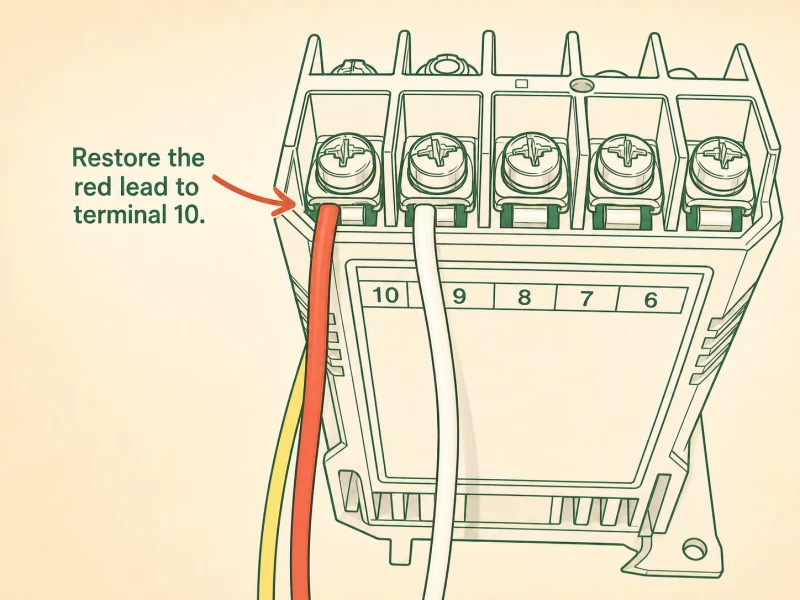
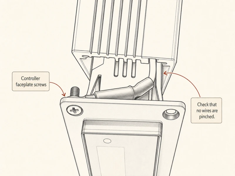
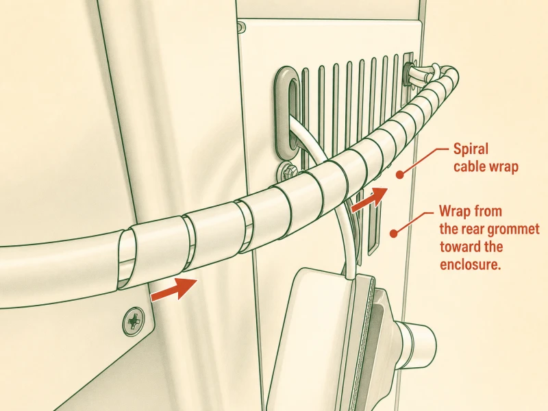
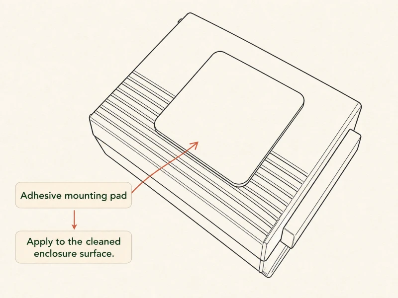
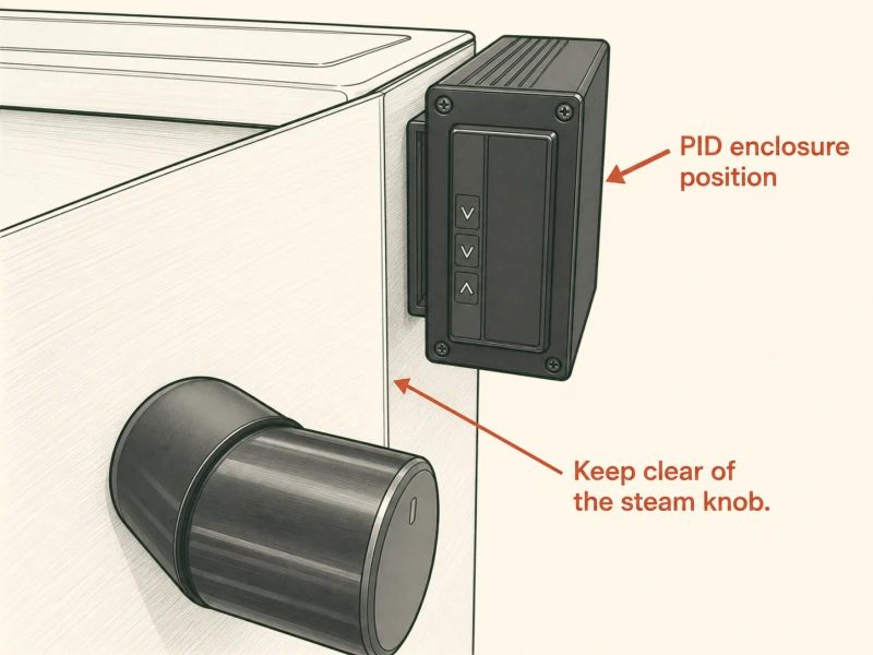
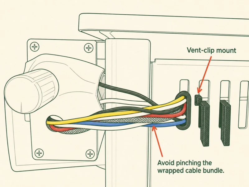
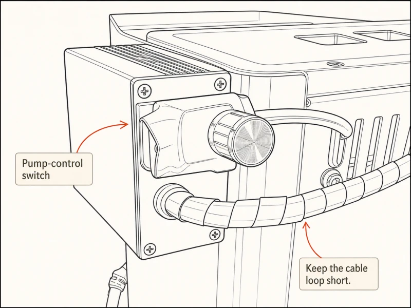
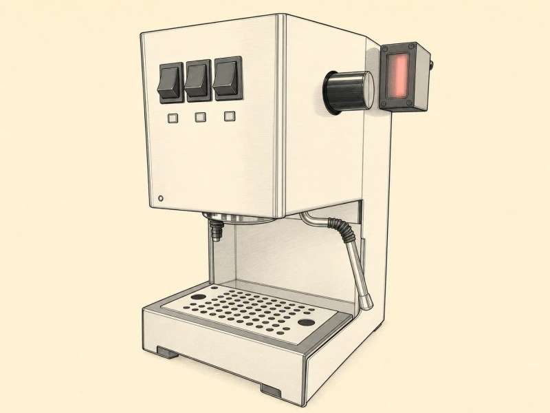
Key takeaway: Reconnect #10 red wire. Move ground ring terminal to permanent post. Four faceplate screws finger-tight then snug. Fifteen-minute burn-in: steady within ±1°C means good. Wander means tune P/I/D, not rewire.
Step 29: 2 to 3 Prong Ground Upgrade
Five ground points exist on a Gaggia chassis: two posts on top of the boiler, two tabs on the top cover, one on the pump mount, and one on the new power cable entrance fitting. Run the four yellow female-to-ring wires from the kit in a chain. Route one wire from a top cover tab to the pump mount. Route another from the pump mount to one of the two boiler posts (the one without the factory green/yellow wire). Route a third from the other top cover tab to the power cable entrance fitting. The fourth wire links any two points that aren't already directly connected. Leave the factory green/yellow wire on its boiler post — that's the OEM ground path, and it stays. Redundant ground paths are the whole point of this step. If one wire fatigues or a ring terminal loosens, the other paths catch the case before you do. A floating Gaggia chassis can sit at full mains voltage with no current flowing, and the next person to touch the machine and the kitchen sink at the same time gets a shock. Ground every metal part.
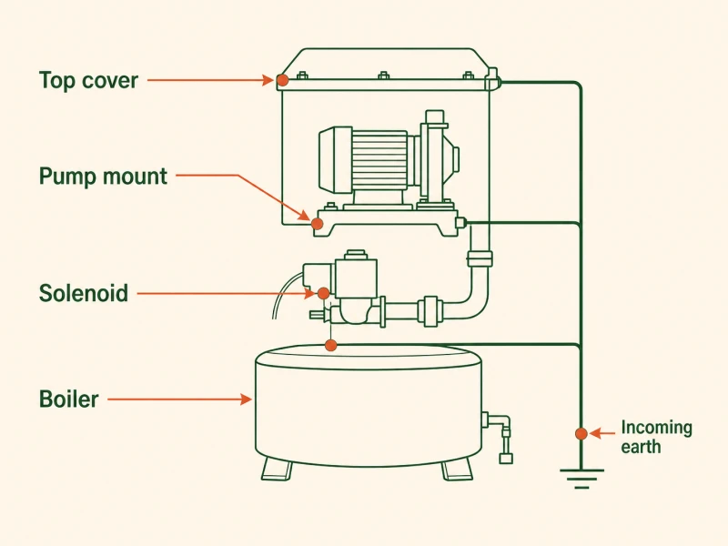
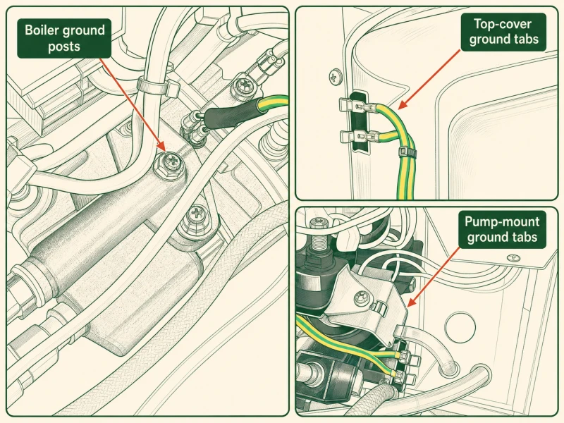
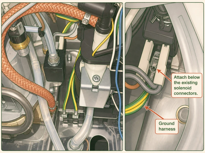
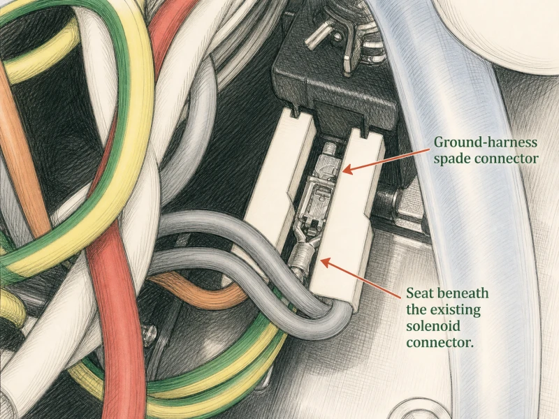
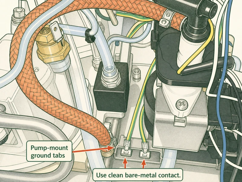
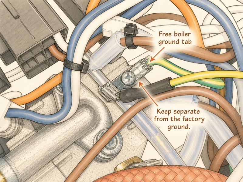
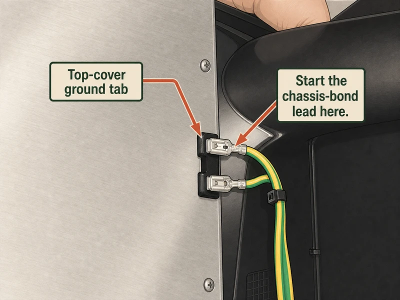
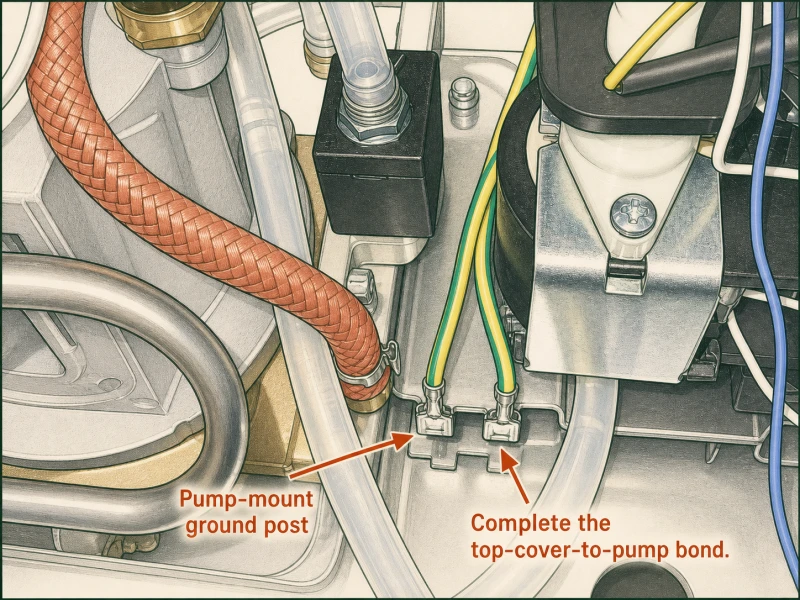
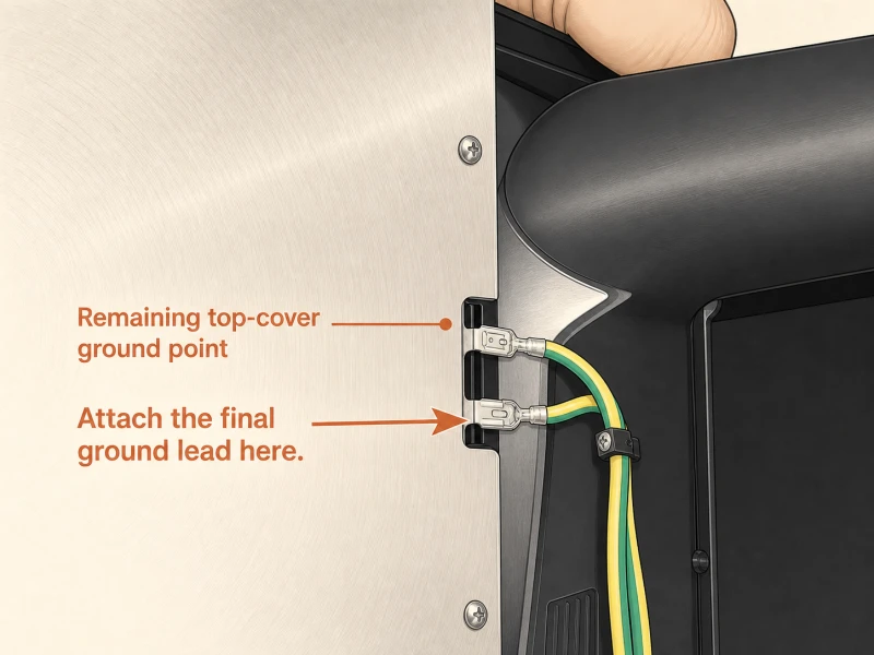
Key takeaway: Five ground points: two boiler posts, two top cover tabs, one pump mount, one power cable entrance. Chain four yellow wires, leave factory green/yellow alone. Redundancy saves lives.
Step 30: Relay Installation Menu
Kits ship one of two relay configurations. Option one: two individual relays loose in the bag, which you mount one at a time using the method from Step 19. Option two: both relays pre-mounted on a black plastic vent clip that slides into the case as a single assembly. The vent clip is faster — snap it into the right vent slots and you're done in thirty seconds. Individual relays give you more placement freedom if your case has an obstruction, a previous mod's wire routing, or a 3D-printed enclosure that doesn't match the vent clip's footprint. Pick your branch based on what shipped in your kit. If your kit includes both options, use the vent clip unless something physically blocks it. Individual relay mounting is covered in Step 19; vent clip mounting is covered in Step 31. Don't mix the two methods on the same machine — pick one and follow it through.
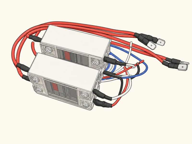
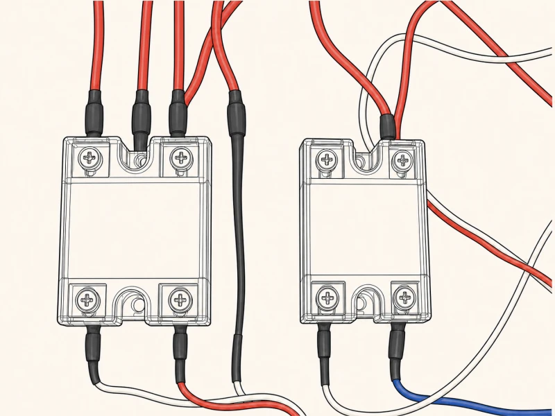
Key takeaway: Two kit types: individual relays (Step 19 method) or pre-mounted vent clip (Step 31). Vent clip is faster; individual relays offer placement freedom. Don't mix methods.
Step 31: Vent Clip Relay Install
The vent clip assembly drops in as one piece. Steam relay sits on the right, brew relay on the left — the clip slides into the second and third vent holes from the right edge of the case. Before you seat it, dab thermal compound on the back of each relay. Same as the individual relay method: the compound fills air gaps between the relay and the case steel so heat transfers properly. Press the clip down into the vent slots until both sides click into place. You'll feel the plastic tabs engage the vent slot edges. If the clip doesn't seat flush, check for a bent tab or a case edge that's been deformed by a previous mod. Forcing a vent clip past an obstruction cracks the plastic, and a cracked clip rattles loose under pump vibration. If the clip won't seat cleanly, fall back to the individual relay method from Step 19. Both methods produce the same electrical result; the clip just saves time when the case cooperates.
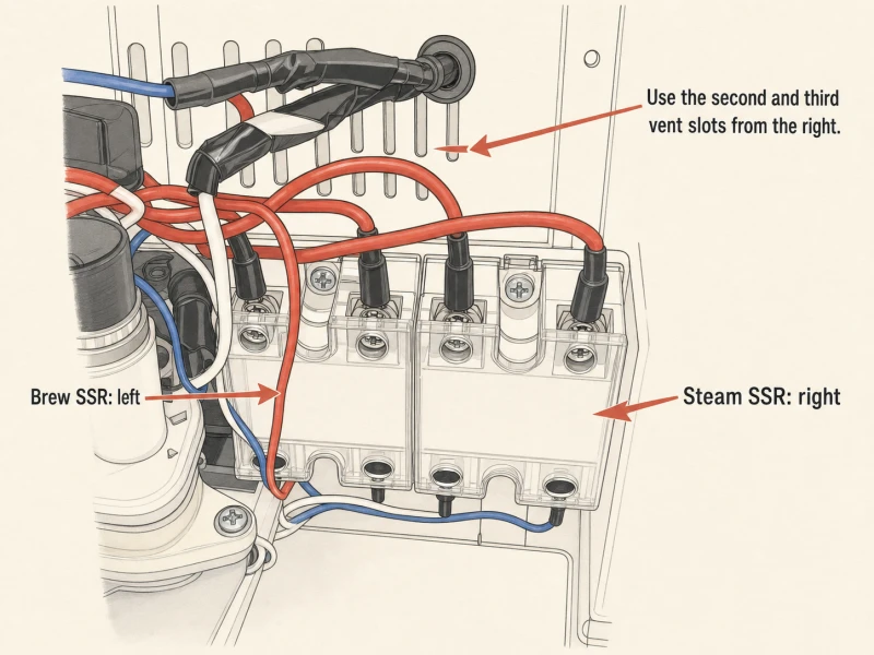
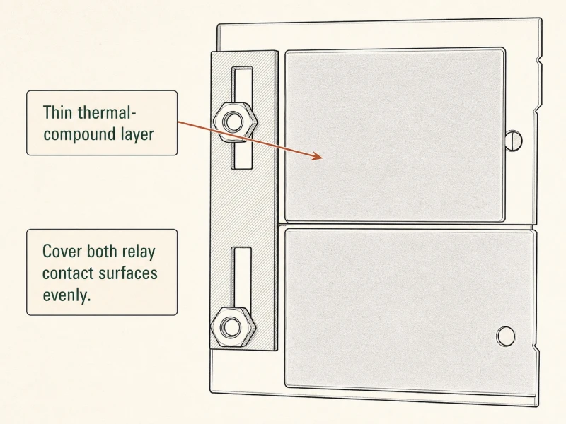
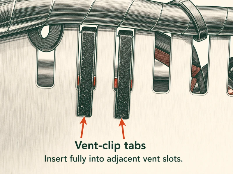
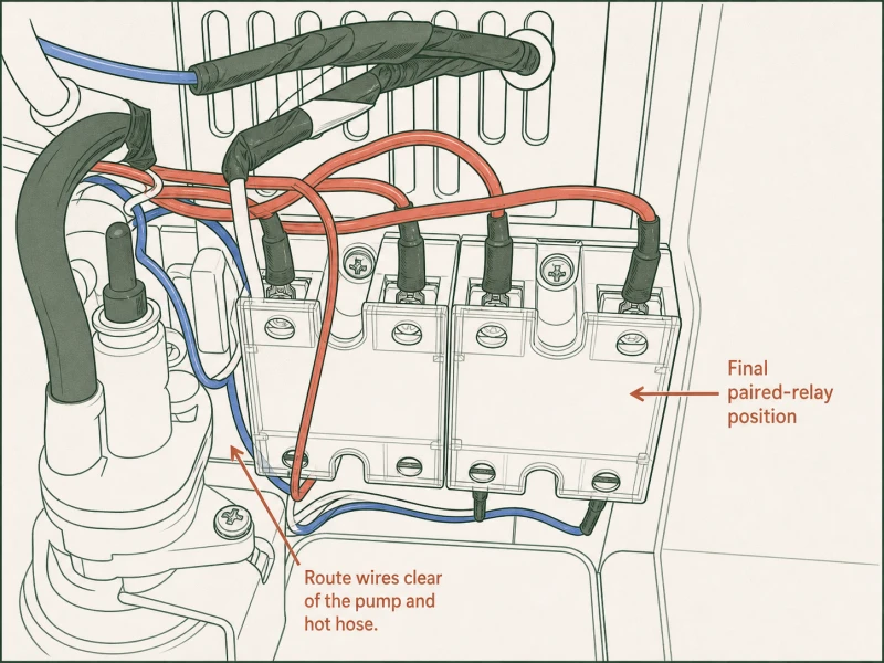
Key takeaway: Vent clip: steam right, brew left, slides into 2nd and 3rd vents from right. Thermal compound on both relay backs. Press until clip clicks. Fall back to individual relays if blocked.
Step 32: Understanding Your PID Controller
Press SET on the controller face to enter parameter mode. Use the greater-than, down-arrow, and up-arrow keys to scroll through the parameter list. Press SET again to confirm any value you change. The default parameters shipped in the controller are sane for a Gaggia boiler — they were tuned at the factory for this exact thermal mass and heating element wattage. Don't go changing P, I, or D values until you've run the machine for a full week and actually observed what the temperature curve does under real brewing loads. A stable 93 degrees Celsius brew temperature and 145 degrees Celsius steam temperature is what you're after. If the brew temp holds within one degree across a thirty-second shot, the defaults are correct. If you see overshoot or slow recovery after a shot, then adjust — one parameter at a time, small increments, test between each change. For starting-point temperatures across different roasts and bean styles, the PID溫度參考 has the full chart.
Key takeaway: Press SET to enter params, arrows to scroll, SET to confirm. Defaults are factory-tuned — don't change P/I/D until you've brewed for a week. Target: 93°C brew, 145°C steam.
Where this guide draws from
This walk-through follows the standard Gaggia Classic Pro / Evo Pro PID install sequence. For another detailed photo walk-through, see the reference below (external, opens in a new tab - their content is their own).
PID install questions, answered
Can I install a PID on an Evo Pro?
Yes. The Evo Pro uses the same aluminum boiler, same case, and same grouphead as the Classic Pro. The only difference lives in the rocker switch wiring — the Evo Pro's toggled-side neutral is accessible for a piggyback spade after a simple top-to-bottom swap at Step 15. The Classic Pro buries that wire, requiring a double swap beforehand at Step 16. Every other step — boiler removal, thermostat swap, RTD install, relay mounting, controller wiring — is identical between the two machines. If you can install a PID on a Classic Pro, you can install one on an Evo Pro.
What's the best PID temperature for Gaggia?
Start at 93 degrees Celsius for brew and 145 degrees Celsius for steam. Those are the factory-tuned defaults that work for medium roasts in a 100ml aluminum boiler. Darker roasts often taste better at 90-91°C because lower heat tames bitterness. Lighter roasts may want 95-96°C to push extraction past the density wall. Steam at 145°C gives enough pressure for microfoam without milk-scorching temperature. Adjust in one-degree increments, pull three shots at each setting, and read the results before changing again. The full temperature reference chart across roast levels and bean origins is on the PID溫度起始點 page.
How do I know if my PID is working?
Three checks. One: the controller powers on and displays a live temperature reading that matches ambient room temperature within a degree or two. If it reads -50 or 999, your thermocouple wires are crossed or loose at the controller terminals. Two: the temperature climbs steadily toward your setpoint when you power on the machine, then holds within plus or minus one degree Celsius. Wild swings or a reading that never stabilizes means a tuning issue, not a wiring fault. Three: pull a shot and watch the temperature dip no more than two to three degrees during extraction, then recover to setpoint within thirty seconds. If the temperature drops five degrees or more during a shot, the RTD sensor has poor thermal contact with the boiler — recheck the compound and thread seating from Step 13.
Can I skip the 2-to-3 prong ground upgrade?
Only if your machine already has a three-prong cable. Two-prong Gaggias have no chassis ground — the case floats at whatever voltage the leakage current produces. A floating chassis can sit at full mains voltage with no current flowing, and touching the machine and a grounded surface (sink, stove, counter edge) simultaneously delivers a shock. The ground retrofit at Step 29 adds redundant ground paths from every metal part back to the power cable entrance. It takes twenty minutes and costs nothing beyond the wire already in your kit. If your machine is two-prong, do Step 29 before you plug in the PID. No exceptions. If you're unsure about any part of the ground retrofit, talk to us before you plug in.
What's the difference between SSR-DA and SSR-AA relays?
SSR-DA is a DC-controlled AC-output solid-state relay — the controller sends a low-voltage DC signal to switch the AC mains load. SSR-AA is an AC-controlled AC-output relay — the controller sends an AC signal to switch the AC load. In this kit, the SSR-DA (red and red wires) handles the brew boiler because the PID's brew output terminal is DC. The SSR-AA (blue and white wires) handles steam because the PID's steam output terminal is AC. You cannot swap them — a DC-controlled relay won't respond to an AC control signal, and vice versa. The relay type is printed on the case. If you mix them up, the controller will command heat but the relay won't switch, and the boiler stays cold. Check the label before mounting at Step 19.
Kit installed? Pull the first shot.
Set a starting temperature, pull a shot, read it, adjust. If you're stuck, talk to us about your install.
 English
  Italiano
  Deutsch
  Español
  Français
  العربية
  日本語
日本語  한국어
한국어  香港中文
香港中文  Nederlands
  Português