
Gaggiuino Gen 3 PCBv4: what to know before you build
This planner helps you confirm whether your Gaggia Classic can run Gaggiuino Gen 3 on PCBv4, and which wiring and UI path fits your machine. It is a pre-build selection guide — not a step-by-step install. Gaggiuino is an L3 mains-voltage modification; full install steps wait on verified in-house hardware.
Gaggiuino Gen 3 PCBv4 for Gaggia Classic: Compatibility and Build-Path Planner
This is a pre-install compatibility and build-path planner for Gaggiuino Gen 3 PCBv4 across the Gaggia Classic family: Original Classic, Classic Pro, Classic Pro Eco, Evo Pro, and E24. It helps you confirm your machine identity, select the correct generation, PCB revision, UI path, and wiring path, and understand machine-specific exceptions before you buy a kit or open the chassis.
This guide does not contain complete installation steps. It deliberately omits per-terminal wiring, line-by-line harness routing, Eco universal bypass procedures, community-sourced wire lengths or connector substitutions, and first power-on sequences. A full L3 iFixit step-by-step guide remains Blocked until HomeBaristaMods holds original real-machine evidence for at least one locked sample.
What this guide solves: machine identity confirmation, the 12-row compatibility matrix, Gen vs PCB revision naming, Screen vs Headless UI choice, Stock Wiring vs Custom Harness selection, machine-specific exceptions (Eco, 120V Evo/E24, Original GC grounding), official BOM categorization, and L3 stop conditions.
What this guide does not solve: complete wire routing, per-terminal pinouts, Eco universal bypass, first power-on validation, and any path that requires real-machine verification HomeBaristaMods has not yet completed.
Official documentation access date for all references in this guide: 2026-07-17.
Confirm Your Machine Before Anything Else
Three independent checks must agree before you select a kit or wiring path. Do not rely on wire color, seller listing, or memory.
- Nameplate model ID: Locate the rating plate. Record the full model code, including suffix (e.g. RI9380/11, RI9480/01). Partial codes such as bare "RI9481" are not sufficient because regional variants exist.
- Voltage: Confirm 100-120V or 220-240V from the plate. Voltage determines OPV behavior, Eco PCB likelihood, and wiring path.
- Eco PCB presence: Open the chassis and visually confirm whether an Eco PCB is installed. The Eco PCB enforces an auto-shutoff and changes the recommended wiring path. Do not infer Eco status from the model code alone.
Model ID reference (per current Gaggiuino compatibility table)
- RI9380 / SIN035R: primarily 100-120V GCP, Evo, E24; a less common 220-240V non-Eco GCP variant also exists.
- RI9480 / SIN035UR: 2019-2022, 220-240V GCP Eco.
- RI9481 / SIN035UR: in the Gaggiuino table, corresponds to 2023+, 220-240V Evo/E24 Eco.
12-Row Compatibility Matrix
Verified against the official Gaggiuino compatibility table on 2026-07-17. Where official data is incomplete, the cell is marked "Unverified" rather than guessed.
| Machine | Model ID | Years | Voltage | Region | Eco PCB | Recommended Gen | Wiring Path | Known Exception |
|---|---|---|---|---|---|---|---|---|
| Original Gaggia Classic | SIN035 / RI9303 | 1991-2014 | 220-240V | Not subdivided | No | Gen 3 / PCBv4 | Stock or Custom | None specific |
| Original Gaggia Classic | SIN035 / RI9303 | 1991-2018 | 100-120V | US etc.; exact region unverified | No | Gen 3 / PCBv4 | Stock or Custom | Most US units need grounding |
| 2015-2018 Classic, 100-120V | SIN035 / RI9303 | 2015-2018 | 100-120V | Unverified | No | Gen 3 / PCBv4 | Stock or Custom | Must confirm it is not RI9403 V2 |
| Classic V2 | SIN035U / RI9403 | 2015-2018 | 220-240V | EU etc. | Unverified | Not recommended | No official path | No three-way valve version; excluded officially |
| Classic Pro | SIN035R / RI9380 | 2019-2022 | 100-120V | US etc. | No | Gen 3 / PCBv4 | Stock or Custom | No additional exception |
| Classic Pro non-Eco | SIN035R / RI9380 | 2019-2022 | 220-240V | Officially rare; region unverified | No | Gen 3 / PCBv4 | Stock or Custom | Do not conflate with RI9480 Eco |
| Classic Pro Eco | SIN035UR / RI9480 | 2019-2022 | 220-240V | EU/WE | Yes | Gen 3 / PCBv4 | Custom recommended | Power switch handling; Stock not recommended |
| Evo Pro | SIN035R / RI9380 | 2023-2024 | 100-120V | US etc. | No | Gen 3 / PCBv4 | Stock or Custom | OPV 10-12 bar; terminal insulation for Stock |
| Evo Pro Eco | SIN035UR / RI9481 | 2023-2024 | 220-240V | EU/WE | Yes | Gen 3 / PCBv4 | Custom recommended | Power switch handling |
| E24 | SIN035R / RI9380 | 2024-end unverified | 100-120V | US etc. | No | Gen 3 / PCBv4 | Stock or Custom | OPV 10-12 bar; terminal insulation for Stock |
| E24 Eco | SIN035UR / RI9481 | 2024-end unverified | 220-240V | EU/WE | Yes | Gen 3 / PCBv4 | Custom recommended | Power switch handling |
| E24 Australia variant | RI9481 / SIN035R | 2024-end unverified | 220-240V | AU | Unverified | Hold until real-machine confirmation | Unverified | Gaggia AU manual suffix conflicts with Gaggiuino table |
Gen 3 Is Not the Same as PCBv4
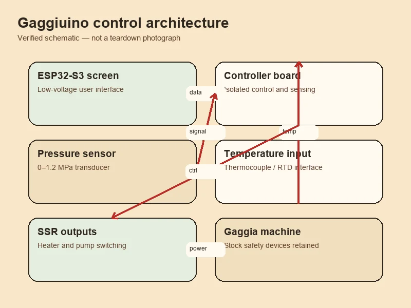
A common error is treating generation numbers and PCB revision numbers as the same axis. They are independent.
- Generation (Gen 2 / Gen 3): refers to the firmware and hardware feature set. Gen 3 is the current recommended path for Gaggia Classic and Rancilio Silvia variants. Gen 2 is primarily retained for unofficial compatible machines and stable legacy code paths.
- PCB revision (PCBv3.1 / PCBv4): refers to the physical board design. Gen 3 recommends PCBv4. Gen 2 recommends PCBv3.1. The labels "V3" and "V4" on community kits do not correspond to "third generation" and "fourth generation."
Current recommendation: Gen 3 + PCBv4. PCBv4 remains the current recommended hardware. The latest release still ships STM32U585 performance-pcb firmware (release v.82d3b06, dated 2026-06-23).
MCU firmware and UI build must be synchronized. Flashing mismatched hardware binaries causes abnormal behavior. Firmware older than 2025-02-16 must pass through a specified breaking-update chain before reaching the current branch.
Screen vs Headless
Gen 3 offers two UI paths. You must pick exactly one, and it must come from the current official supplier path. The ESP32 UI must be vendor-enabled; a generic ESP32-S3 board cannot be substituted.
| Path | Hardware | Interface | Notes |
|---|---|---|---|
| Screen | 4.3" ESP32-S3 IPS display | On-machine embedded UI + Web UI | Requires chassis-mounted display cutout or 3D-printed enclosure |
| Headless | E177 PCB | Web UI only | Connects to the same interface port as the Screen; no local display |
Both paths belong to Gen 3. The choice affects physical installation, enclosure design, and whether the machine can be controlled without a network. Headless depends on reliable local network access to the Web UI.
Stock Wiring vs Custom Harness
Both paths use 3PLN and SSR integration. The difference is how much of the original harness you keep.
- Stock Wiring: taps into the original harness with a small number of jumpers. Fewer new wires, but identifying original connections can be more confusing and some machines require terminal insulation work.
- Custom Harness: fully replaces the original harness. More labor, but the finished result is cleaner and more direct. Required for 220-240V Eco machines.
Official recommendation by machine family:
- 220-240V Eco PCB machines (GCP Eco, Evo Eco, E24 Eco): Custom Harness recommended. Stock Integration is not the official path. Power switch handling is required.
- Non-Eco machines: Stock or Custom, with machine-specific exceptions noted in the next chapter.
Three Exception Families You Cannot Ignore
1. Eco machines (220-240V, RI9480 / RI9481)
The Eco PCB enforces an auto-shutoff. Official guidance for 220-240V Eco machines is Custom Harness, not Stock Integration, plus power switch handling. This applies to GCP Eco, Evo Eco, and E24 Eco. A universal Eco bypass procedure is not published here; Eco handling must follow the official machine-specific guide and the real-machine switch type.
2. 120V Evo Pro and E24 (RI9380)
Two official exceptions apply to 100-120V Evo Pro and E24:
- OPV must be adjusted from factory 9 bar to 10-12 bar. This is a mechanical adjustment on the over-pressure valve, not a firmware setting.
- If using Stock Wiring, the combination terminals require insulation handling. This is specific to the Stock path on these machines.
3. Original Gaggia Classic grounding (120V US)
Most US Original Classic units ship with a two-pole power inlet and no protective earth. Official guidance is to add protective grounding and use GFCI / AFCI / RCD protection. This is a chassis and inlet modification, not a firmware or PCB change.
Official BOM Categories Plus What the Kit May Not Include
The official PCB BOM includes the core sensors and switching component. It does not include every harness, enclosure, or tool required for a complete install.
In the official PCB BOM
- Non-grounded K-type M4 thermocouple.
- Pressure sensor, 0-1.2 MPa range.
- SSR-40DA solid-state relay.
Flow meter (inference, not a listed BOM item)
The official BOM does not list a standalone physical flow meter. Gen 3 uses an Ulka E5 pump model with Pump Zero estimation to derive flow. A separate physical flow meter is not required for the standard vibration pump path. This is inferred from the BOM and the Gen 3 user manual; treat it as inference, not an official statement.
Out-of-kit checklist (verify before purchase)
The same "GCP" name can split into 100-120V vs 220-240V, RI9380 vs RI9480 vs RI9481, Eco vs non-Eco, Stock vs Custom, Screen vs Headless, and T-fitting vs Pressure Tap Block. Your out-of-kit list depends on the path. Common items to verify:
- Custom Harness materials (wire, terminals, heat shrink) if your machine is Eco or you chose Custom.
- 3D-printed protective enclosure for the PCB and UI.
- Pressure branch component: T-fitting or Pressure Tap Block, per your machine and path.
- Hose, barb, and clamp combination rated for your pressure branch (follow the BOM; do not substitute community-sourced combinations).
- ST-Link for firmware flashing.
- Crimping tool, pull-test, and insulation verification capability.
- Multimeter rated for your mains voltage.
Do not build a single "one-click buy" bundle across all machines. Pressure branch, harness, and enclosure parts are path-dependent.
Risk Level L3, Required Competency, and Power-Off Conditions
This modification is rated L3. It simultaneously involves mains voltage, the boiler heater, SSR, thermal fuse, internal harness, pump, and pressurized water circuit.
Primary hazards
- 100-240V mains shock and energized chassis.
- SSR or wiring sequence error causing sustained boiler heating.
- Thermal fuse, grounding, or insulation removed incorrectly.
- Pressure branch leak onto PCB, terminals, or SSR.
- Firmware/hardware mismatch causing abnormal control behavior.
- Insulation damage from wires routed near boiler, pump, or sharp chassis edges.
Required user competency
- Confirm machine version from nameplate, schematic, and real hardware, not wire color.
- Crimp, insulate, pull-test, and distinguish AC, DC, and protective earth correctly.
- Perform continuity and resistance checks with the machine fully de-energized.
- Identify reliable hose, fitting, seal, and pressure ratings.
- Know when to stop; do not hot-probe unknown wiring by trial and error.
Required test tools (publishing threshold, not equal to the full official BOM)
- Multimeter rated for local mains voltage.
- Grounding continuity and insulation safety test equipment; final publication should involve a qualified electrical professional.
- Crimping tool, pull-test, and insulation check capability.
- Empty / blocked-basket pressure verification setup.
- Water circuit leak check setup.
- Equipment to record firmware build, pressure, temperature, and SSR state.
Specific pass thresholds depend on machine region and local electrical safety standards. This guide does not fabricate numeric thresholds.
Pre-first-power-on checks
- All low-voltage bench tests pass.
- MCU, Embedded/Headless UI, and Web builds match.
- Pressure reads 0.0 bar with no pressure applied.
- Thermocouple reading changes reasonably when heated.
- SSR indicator logic matches official bench check.
- Protective earth, thermal fuse, and chassis grounding re-confirmed.
- No exposed terminals, pinched wires, heat-affected insulation, or loose crimps.
- Water circuit, pressure branch, boiler, and fittings show no seepage.
- PCB and UI installed in protective enclosure.
- First power-on and first shot recorded on video with readings.
- Machine model, voltage, Eco PCB, or wiring diagram cannot be matched one-to-one.
- You would need to guess L/N, pump, heater, or switch terminals by wire color.
- Firmware builds mismatched or hardware cannot complete bench verification.
- Pressure is non-zero, temperature jumps, or SSR lights abnormally.
- Water leak, hose bulge, loose fitting, or wet electronic parts.
- Original grounding missing, or protective earth confused with DC GND.
- You would need to open the chassis live to continue troubleshooting.
- You do not have the competency to complete grounding and insulation review.
Rollback requirements
- Photograph and label the complete original harness before disassembly.
- Store original harness, thermostat, connectors, Eco parts, and switch parts separately.
- Record every irreversible operation.
- After rollback, re-execute grounding, insulation, thermal protection, and water circuit verification.
- For Custom Harness, "machine powers on again" is not a sufficient rollback success criterion.
Professional review required
Yes, specifically for:
- All 220-240V Eco Custom Harness work.
- Original GC grounding modification.
- Any thermal fuse, SSR, boiler heater circuit, or power inlet modification.
- Final sample machine before HomeBaristaMods publishes an executable L3 guide.
Conditions to Upgrade This Page to a Full iFixit Step-by-Step Guide
The full L3 iFixit installation guide remains Blocked. It will be unlocked only when all of the following are true for at least one locked sample machine (for example: RI9480, 230V, EU GCP Eco, PCBv4, Gen 3 Screen, Custom Harness).
- Original continuous photography exists for pre-disassembly, during installation, and post-installation.
- Every wire is double-checked against both the official schematic for that specific machine and the real unit.
- Low-voltage bench, firmware, grounding, insulation, thermal protection, pressure, leak, and first power-on verification are all complete and recorded.
- Complete BOM, batch, firmware build, anomalies, and rollback records exist.
- A qualified professional with mains-voltage equipment experience has reviewed the build.
- On the day of publication, the current official documentation and the latest firmware release are re-checked.
Not ready to build yet?
Start with the basics: a 9 bar OPV spring and a PID kit cover 80% of real-world Gaggia upgrades without opening the power path.
 English
  Italiano
  Deutsch
  Español
  Français
  العربية
  日本語
日本語  한국어
한국어  香港中文
香港中文  Nederlands
  Português